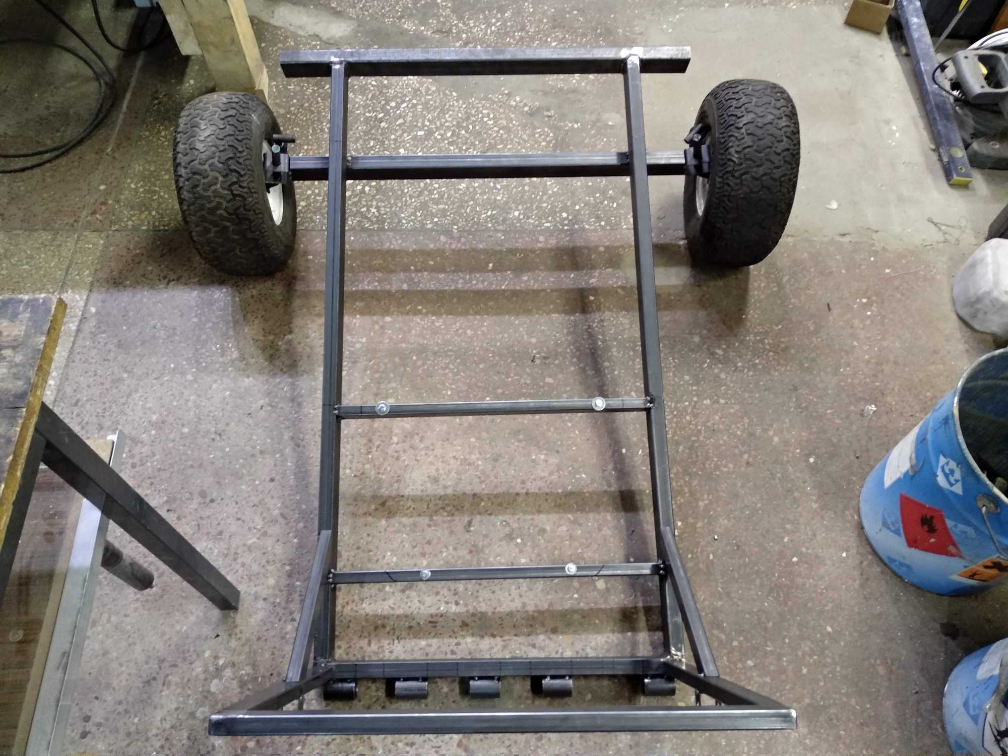
Welp, I never thought I’d be doing this, but making a gokart began when a friend said that he has a kinda brand new 4-stroke, 400cc engine and doesn’t know what to do with it. It was at this moment that I spontaneously said – well let’s make a go-kart then.
I didn’t think much about it and my projects up to that point weren’t so big in size or effort, but anyway, I took it on and I’m glad I did. I learned a lot and having a gokart is LOTSA fun!
I am still making this and this post is a part one where I’ll try to briefly explain things that I did to have a thing that you can actually drive a bit.
When I began I didn’t know anything about how to build one, didn’t know much about how to properly work with metal, didn’t know how to weld and other things, but very much thanks to Kaunas Makerspace and people there I was able to make something.
Without any plans or models, I figure things out as I go from examples I find online either in written form, pictures or videos, and there is plenty of material to see.
Apparently gokart builds are a popular thing in Murica and you can find loads of information on YT, forums or all kinds of websites with sometimes in-depth explanations of how stuff works which was super helpful.
The stock engine
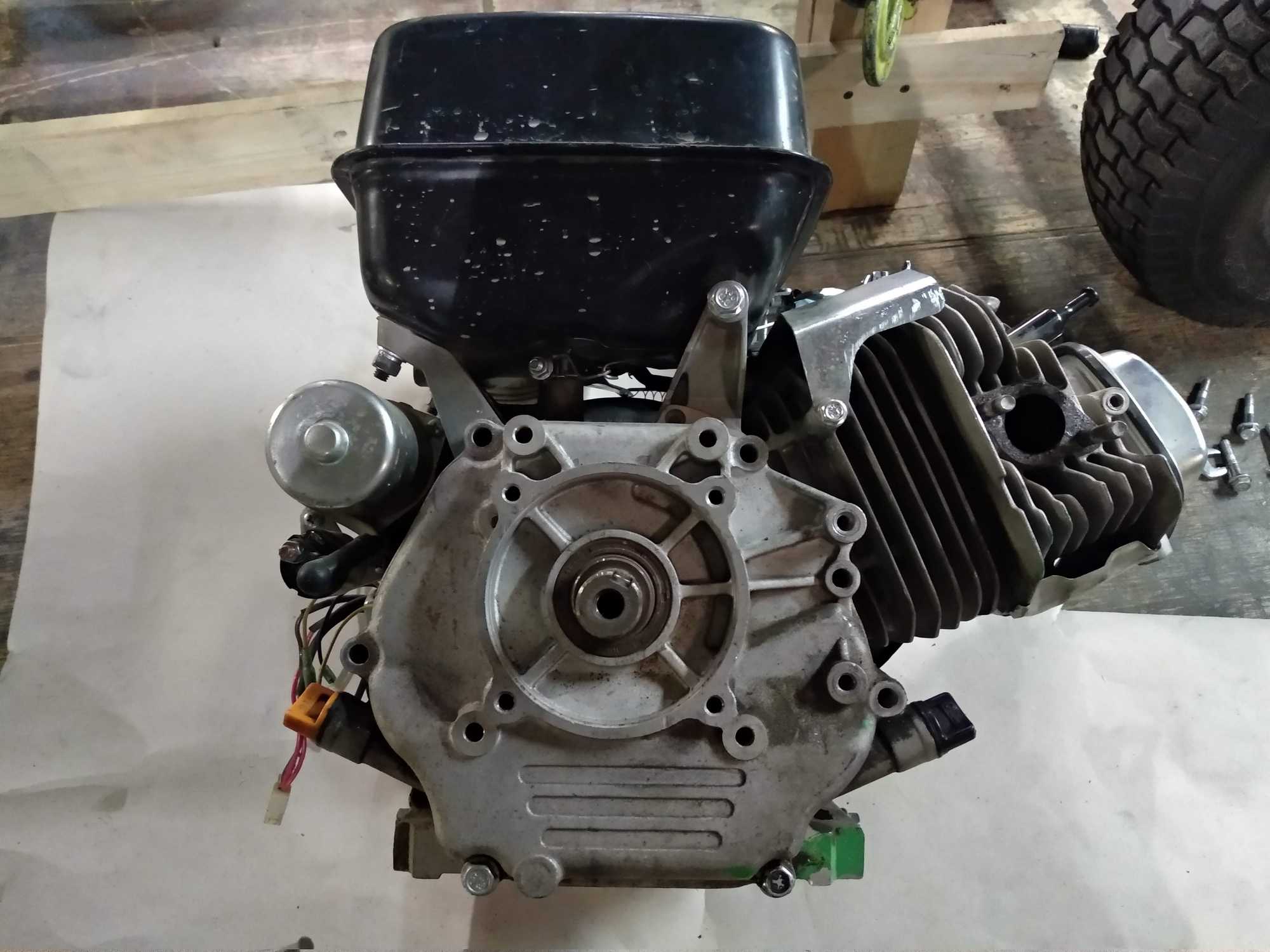
The engine that I got is from a Kipor electric generator. The whole generator somehow broke down but the engine was still very good. The model is Kipor KG390 – 4-stroke, 1 cylinder, 400cc, 11.5 HP, 8.4 kW and 3600 RPM with an electric starter! brand new one costs ~400€
Stock engine like this without ANY modification is not very good at offroading – it’s pretty limited with filters, exhausts and governors… and it’s not made to withstand lots of stress. Some of those things had to be replaced or bypassed to turn on a sports mode.
Engine mods are separated into tiers, and tier 1 is the first and easiest thing to do which is to replace an air filter, main jet, exhaust and some other things on the outside.
The basic things
The very first things I bought was a centrifugal clutch. Without it this wouldn’t work. Surprisingly in Lithuania there’s no where to buy these things that would fit this engine, except for one guy that I found from ads who sells them online.
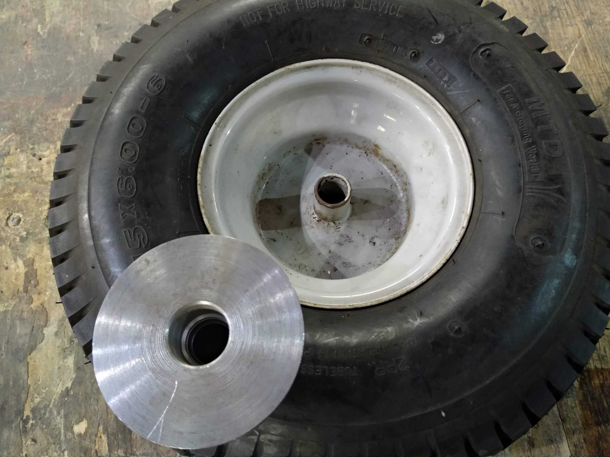
Right away I searched for people who sells lawn mower tractor parts and bought the wheels, a steering wheel and the steering system. Then I bought the metal I’d need to make everything and other small stuff. Also a friend made a seat from fiberglass.
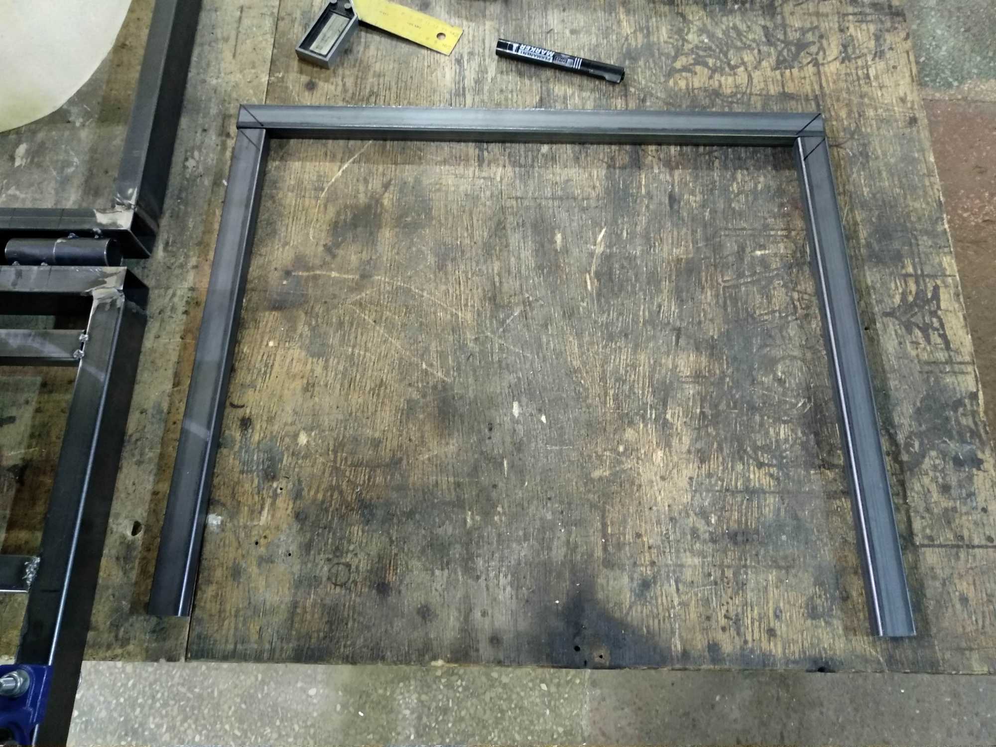
With all the basic things on the table, I went on to sketch out some ideas of how it might come together and what size should it be.
The important thing was to decide if I wanted to make it fast or should it have more power.
I decided that I wanted to have it go up to ~30-35 km/h, that way having more torque, since it’s going to see more offroading. So a friend helped me calculate the transmission sprockets I’d need to put in to have that ratio.
Reduction ratio
The calculation is pretty simple.
You need to know your wheel size in cm (34cm), what speed you want to achieve (30 km/h), maximum engine RPM’s (3600), the teeth number (15) and teeth step size on your clutch (428). With those numbers the reduction ratio I got was 7.7.
To get that much reduction, I’d need to use a sprocket with 108 teeth and with a step of 428 the size of it would be almost the same as the wheel itself.
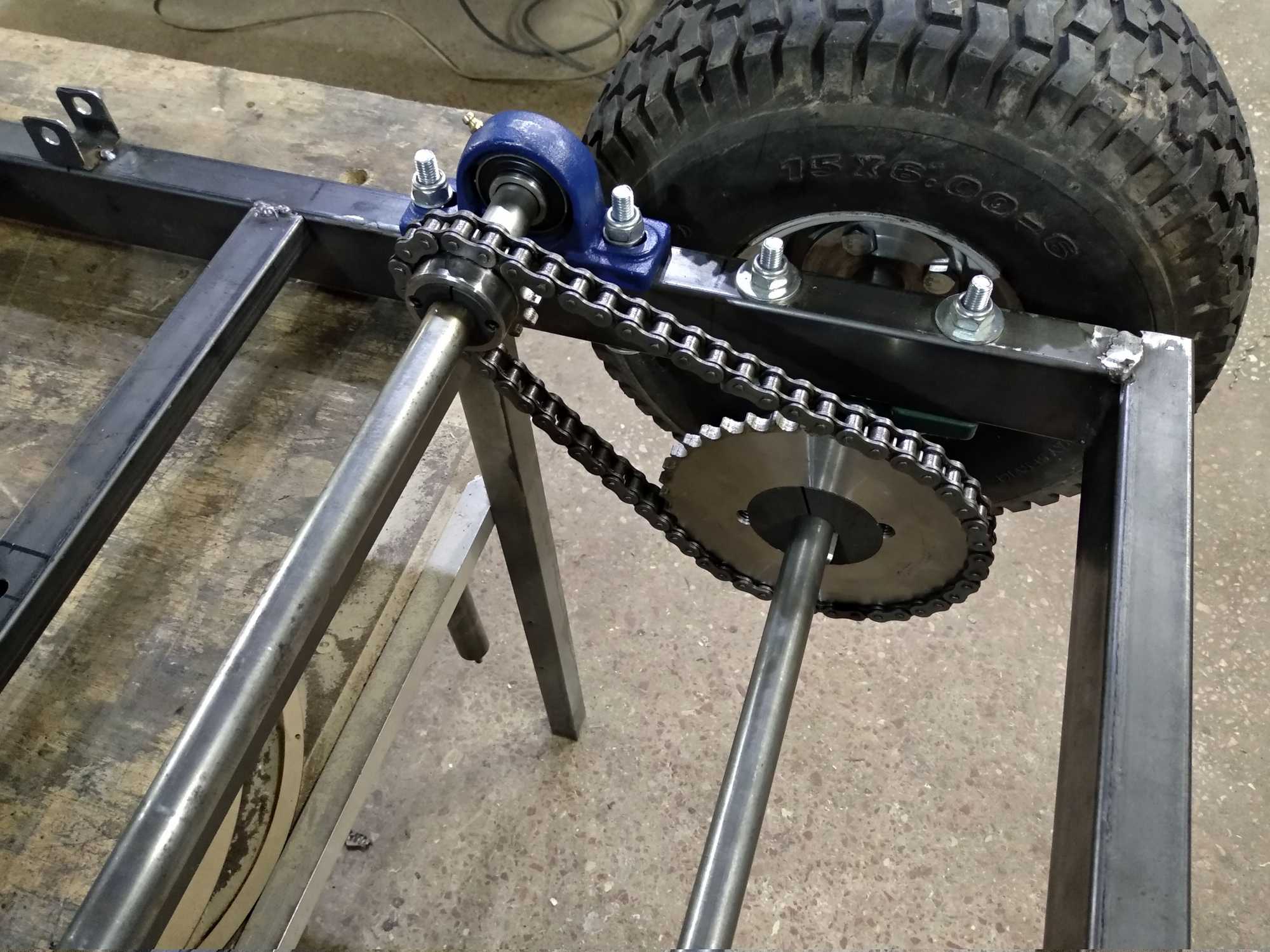
Obviously that’s not good – I want more clearance for offroading. Therefore I need an intermediate transmission to reduce the sprocket size and still have that reduction ratio. The last line shows how to calculate that and I get that I’d need 3 sprockets in total – 2×38 teeth and 1×14 teeth.
Getting it all together
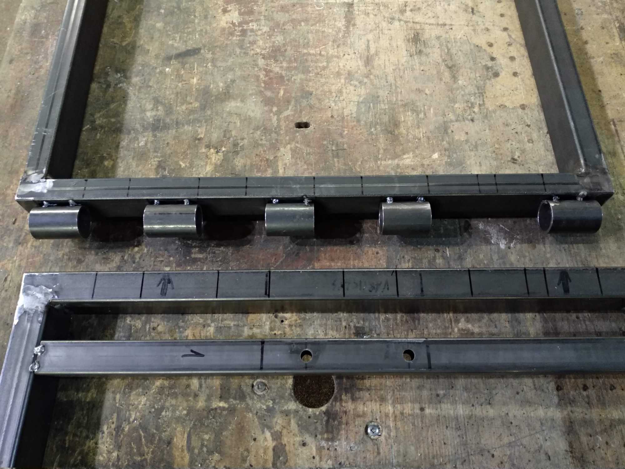
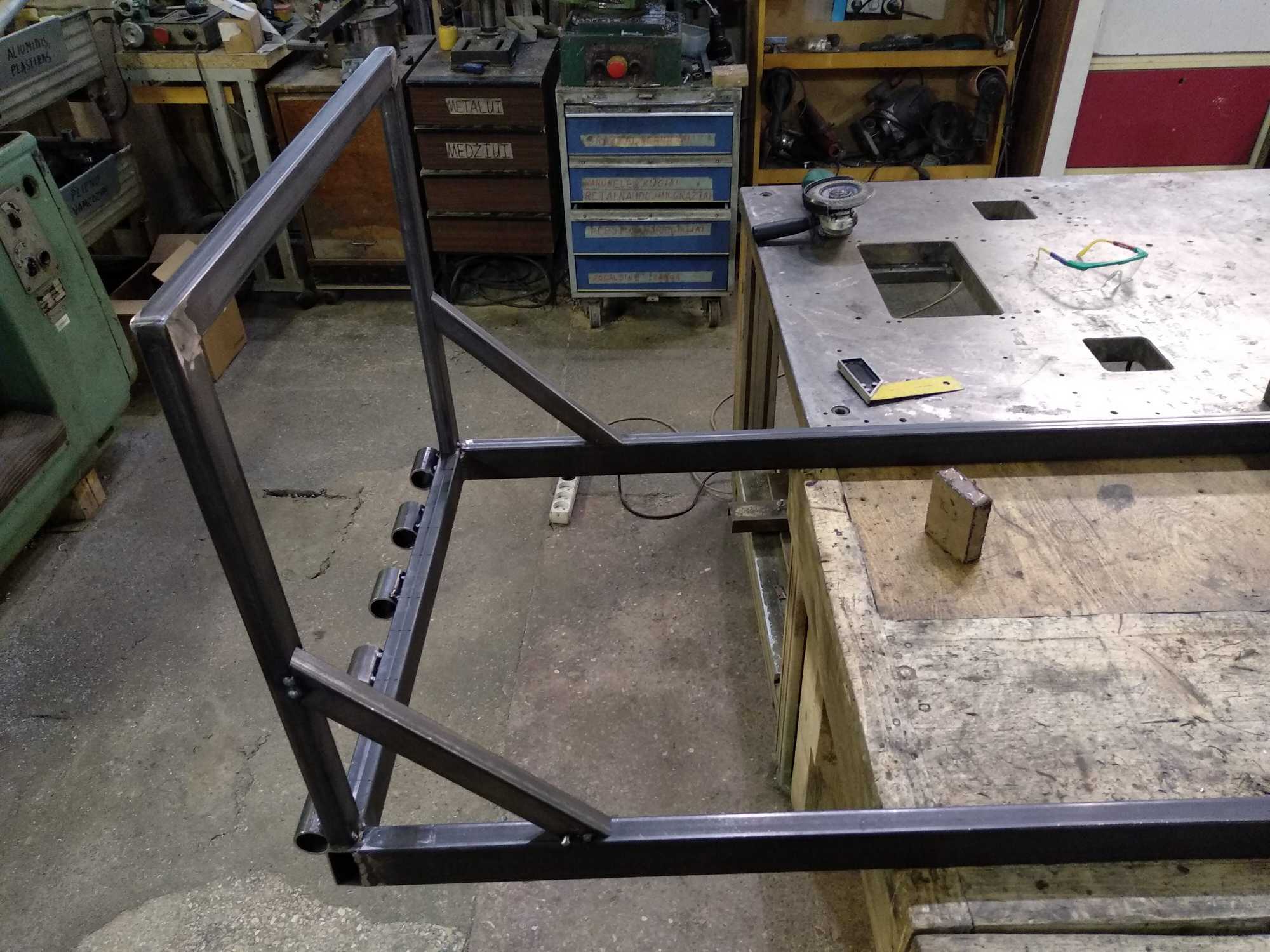
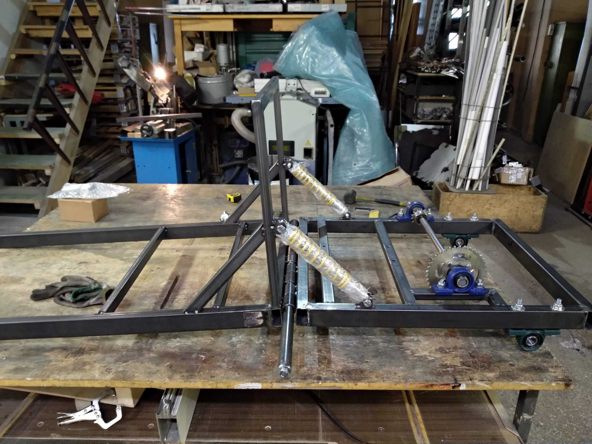
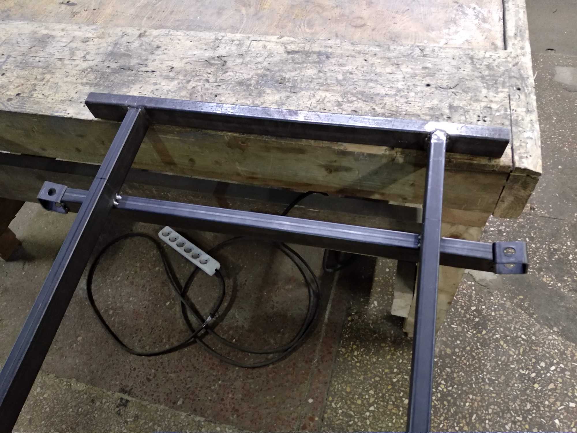
I also wanted to have this go kart with replaceable parts and that I could disassemble it completely if I had to. That means I couldn’t weld everything shut and expect it all not to break one day and after it does cut it up to replace something – that’s pretty stupid.
So I took those extra steps to have parts that I could disassemble easily.
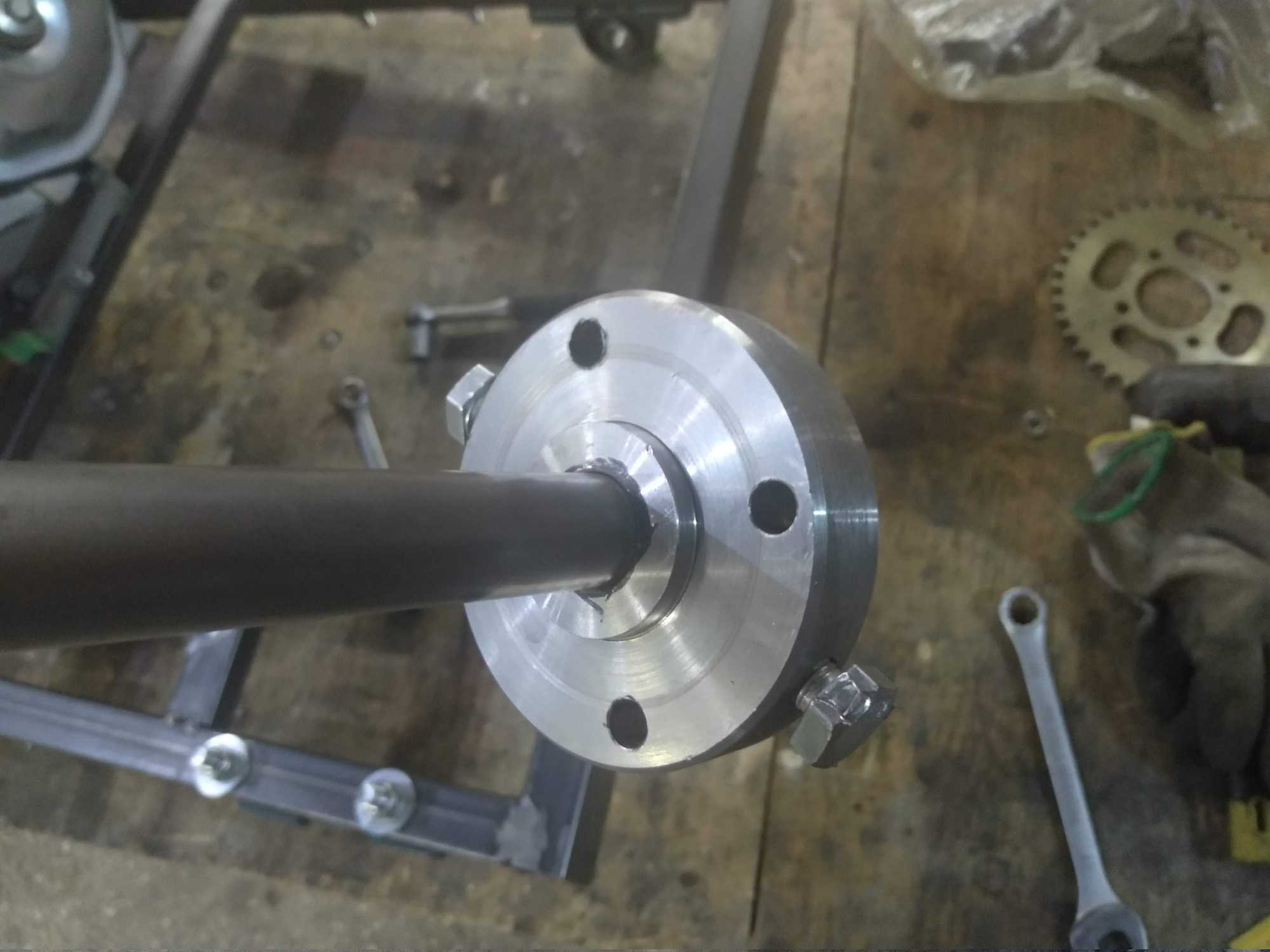
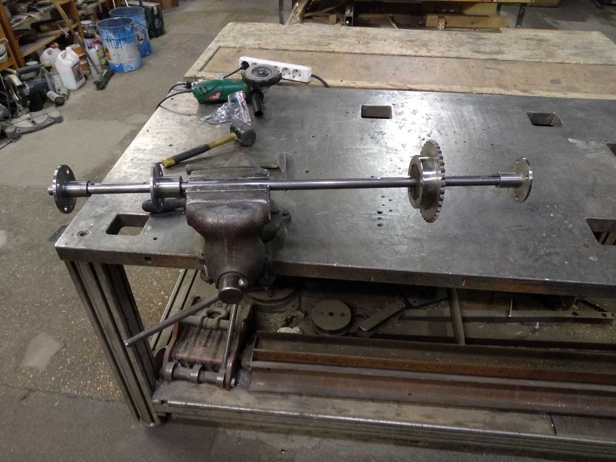
The first sprocket you see above is from a motorcycle. I made a mistake buying it and used sprockets for industrial machines for other ones. Those are much heavier, but can be put on much more easily. For this motorcycle sprocket I had to make a holder and I spent a couple of hours on the lathe making it. Wasn’t worth it at all :D
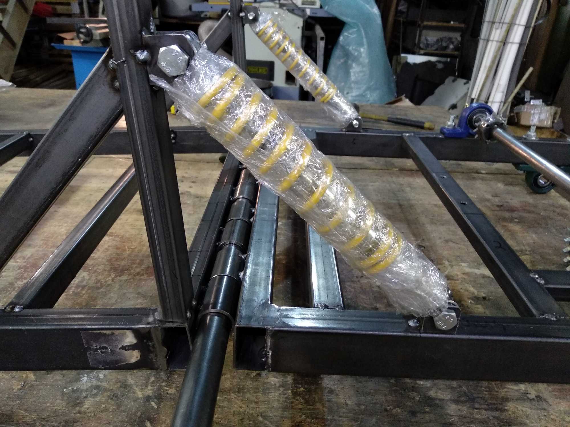
Generally, a go kart doesn’t have any kind of suspension, but I wanted to have at least the body to move for a smoother ride.
Those yellow shock absorbers were cheap, but came with no information and I couldn’t adjust the spring tension.
Eventually I replaced them with a bit better ones that a friend gave me and such a thing works remarkably well – your ass doesn’t hurt on every bump.
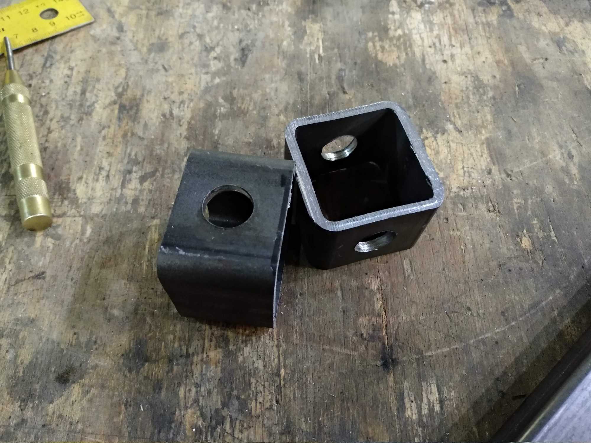
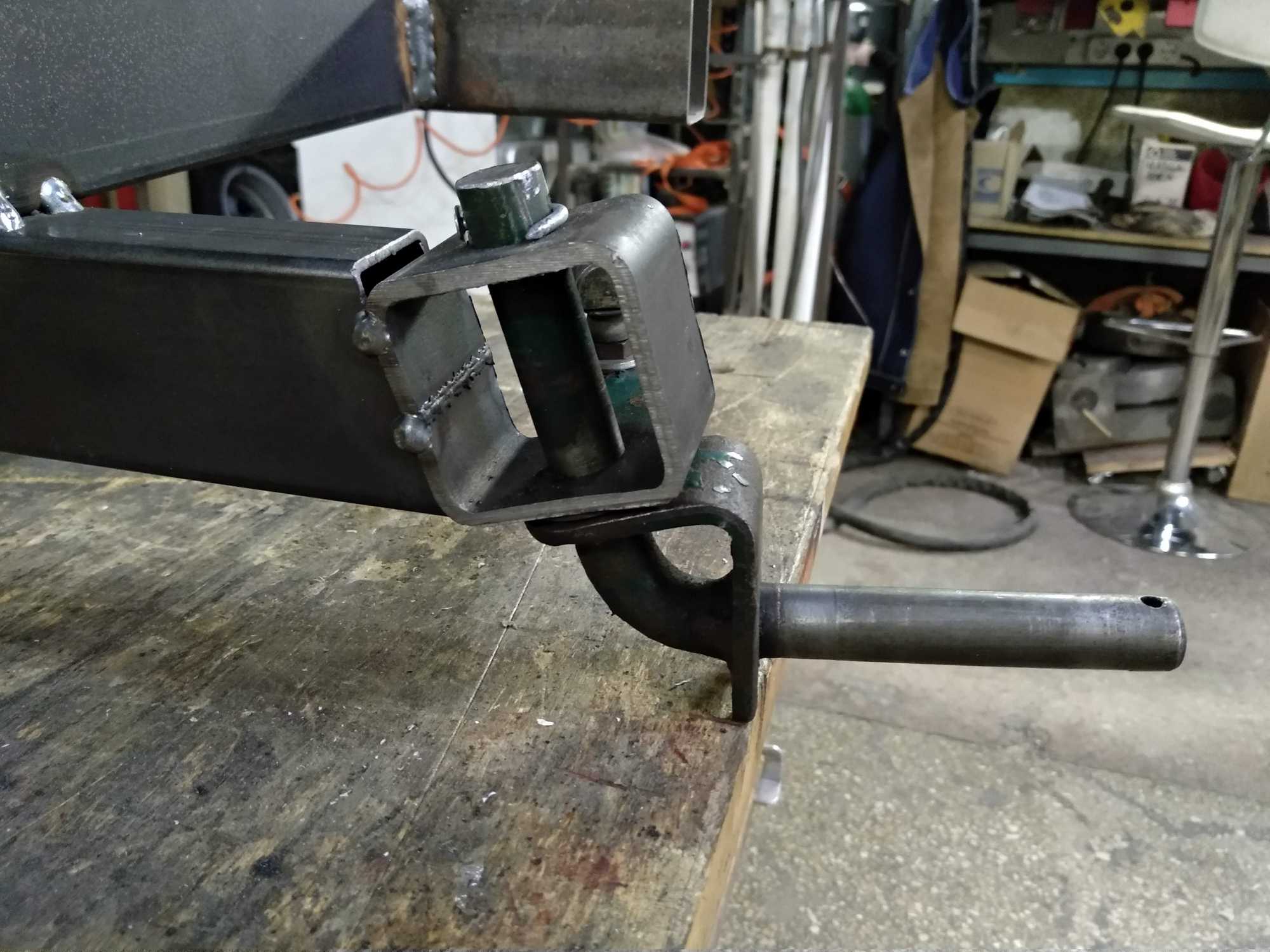
Then came the front wheels. At this moment you might notice that I had cut the ends at an angle. I didn’t get into that whole Ackerman steering theory thing, because honestly I don’t really care because the project isn’t about racing or excellent performance and stuff.
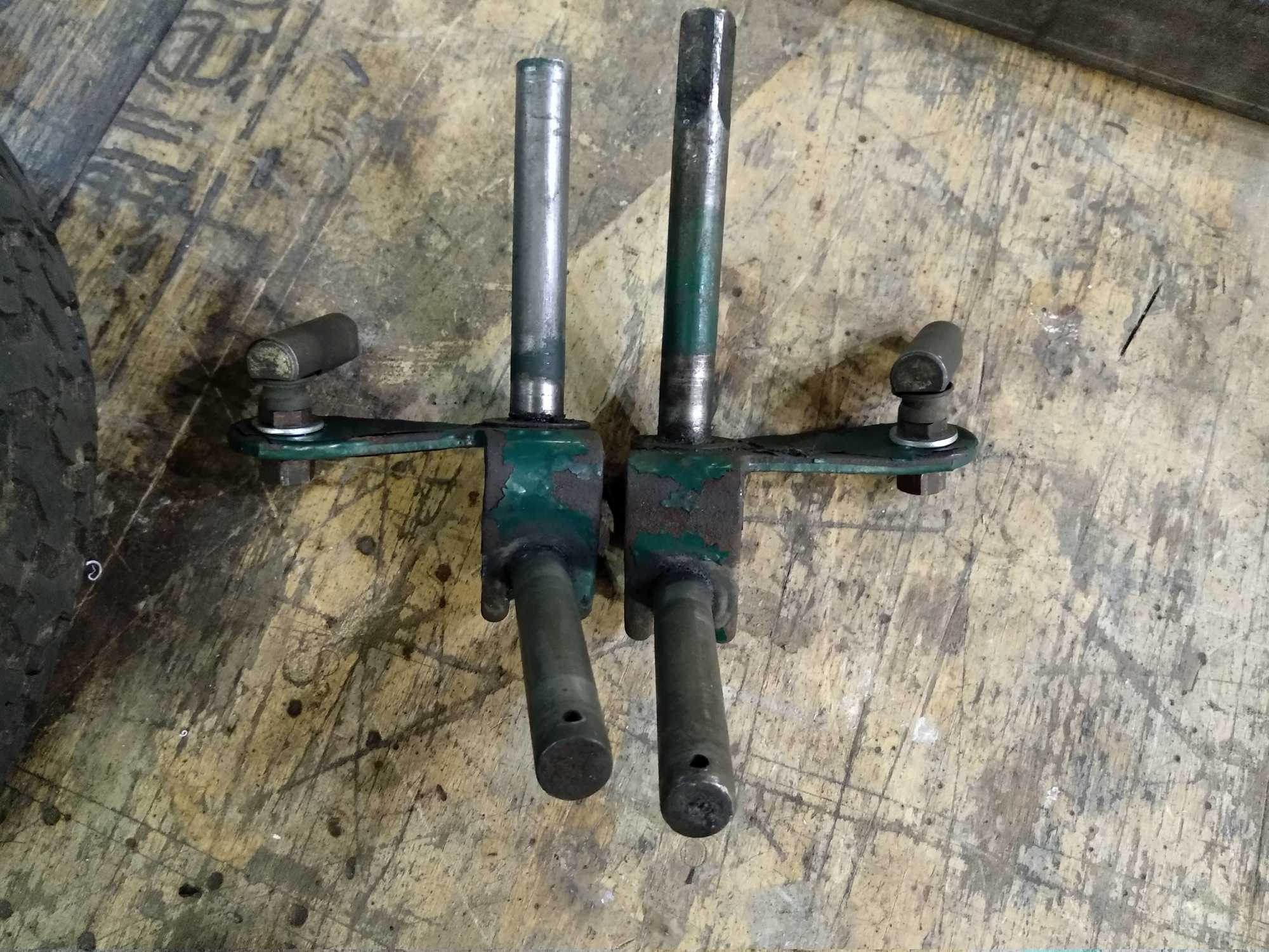
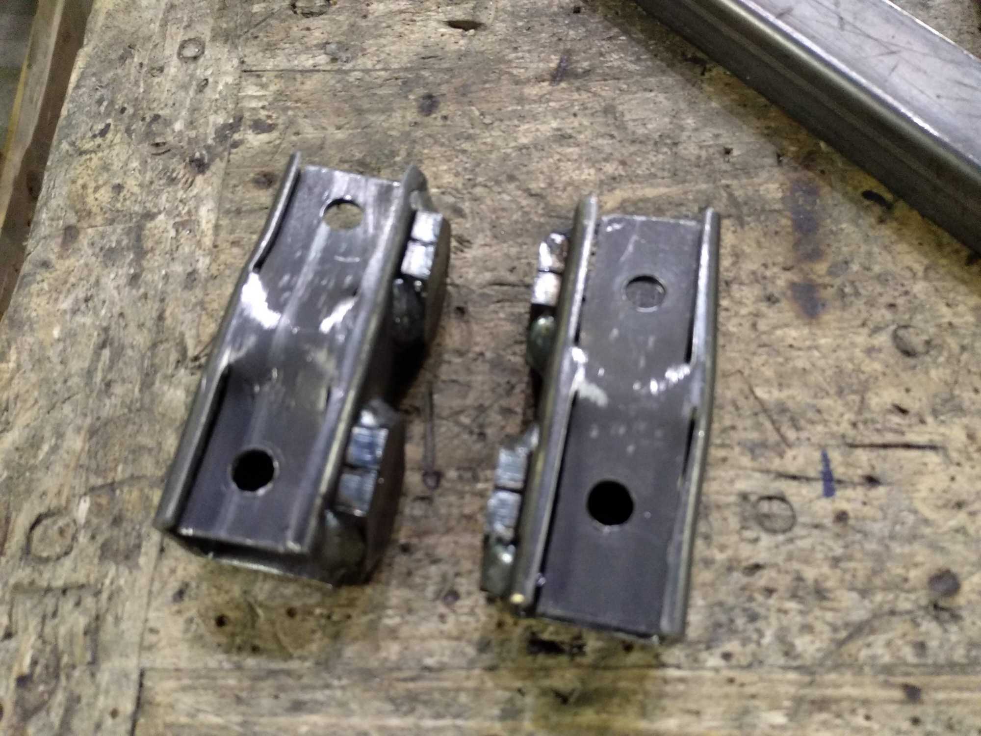
The front wheel holders that I bought were already bent at an angle, so I adapted them thinking that it might fit my situation, since lawn mower tractors are similar in dimensions.
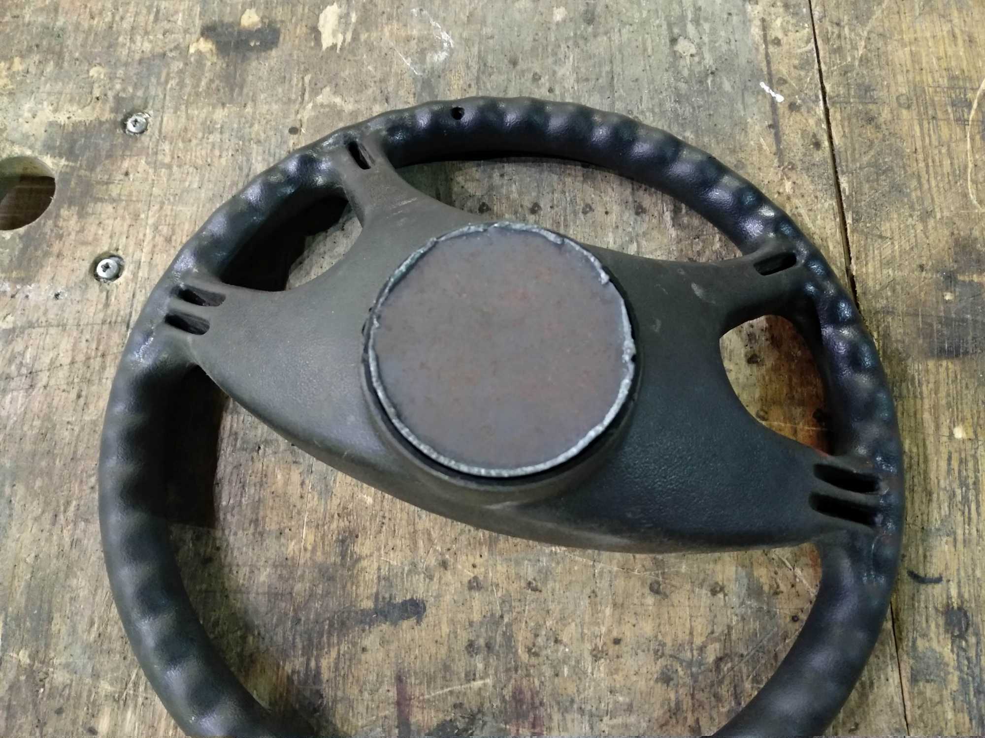
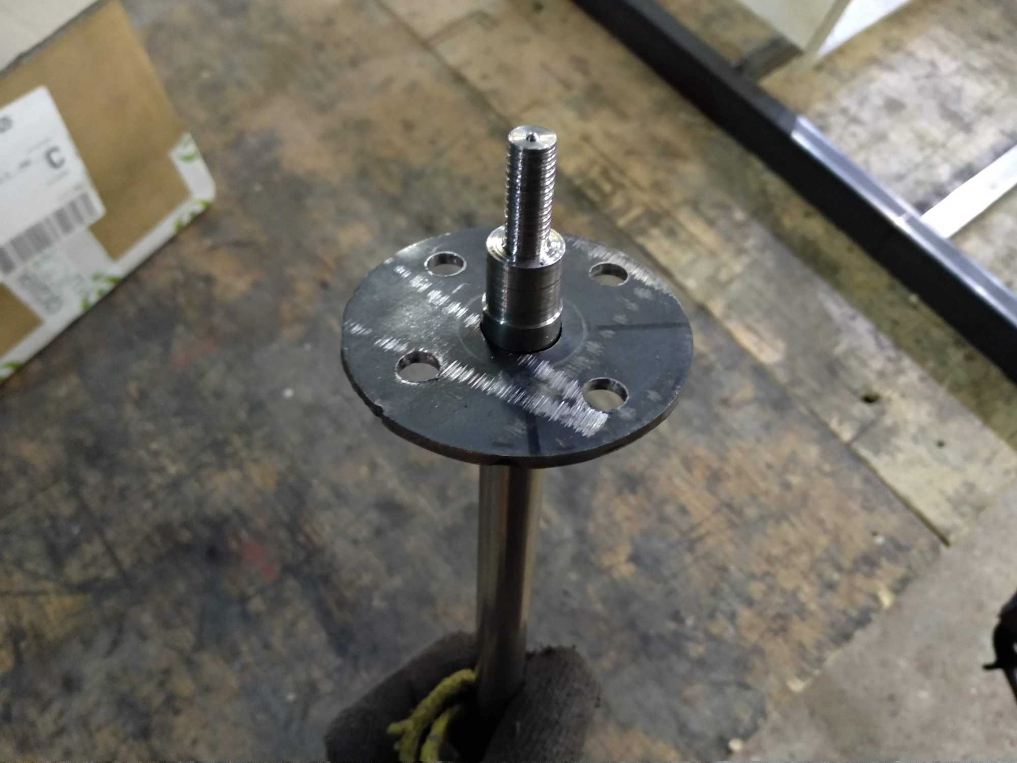
Next was the steering wheel and the whole steering mechanism with adjustable wheels. Here I noticed that it’s impossible to make a gokart comfortable for everyone, therefore I made it comfortable to people of my height and build :P
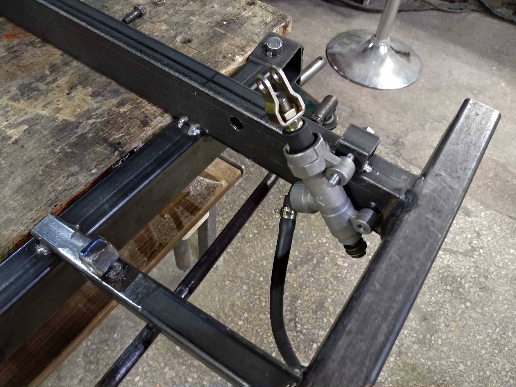
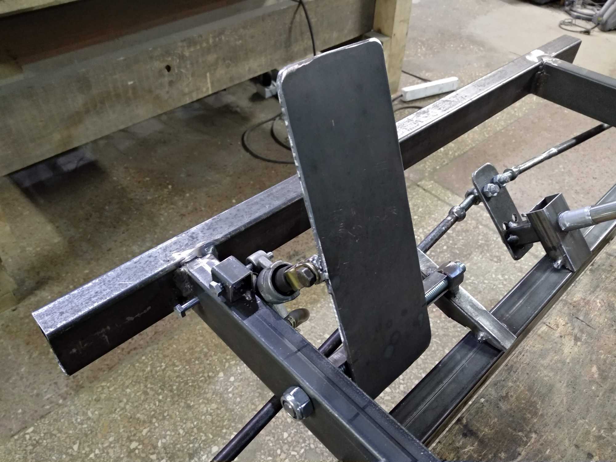
Some kinda pedals for acceleration and braking is needed. The brakes are of course hydraulic – it takes a lot of force to block those wheels because of weight.
Here you can see that I used a small-looking master cylinder. Well, I bought it without knowing that there are different kinds of them and this one in particular is not good for my case because it’s weak. I used a 3m hydraulic hose and that master cylinder wasn’t capable of pressing on the caliper through such a distance. I replaced it later with a much stronger one.
Then I added a caliper and a used brake disc from some scooter that I bought for a couple of euros. The holders for a brake disc and rear wheels were ordered to be made by a friend.
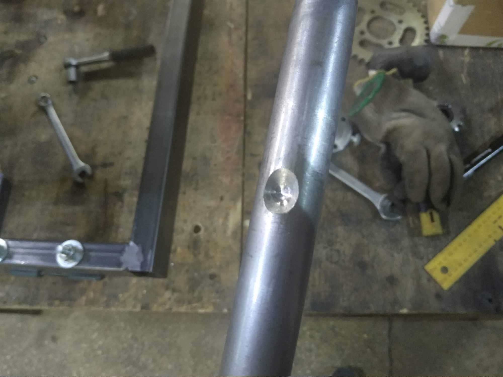
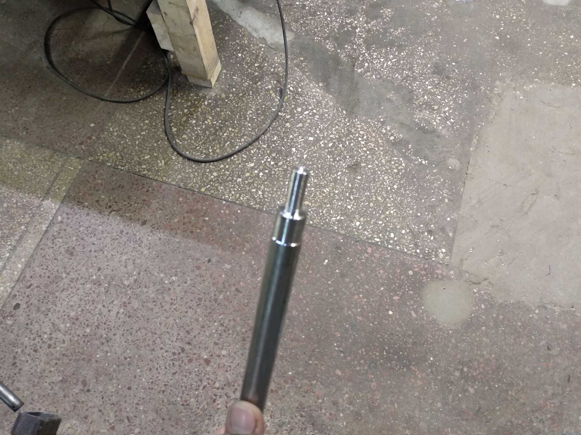
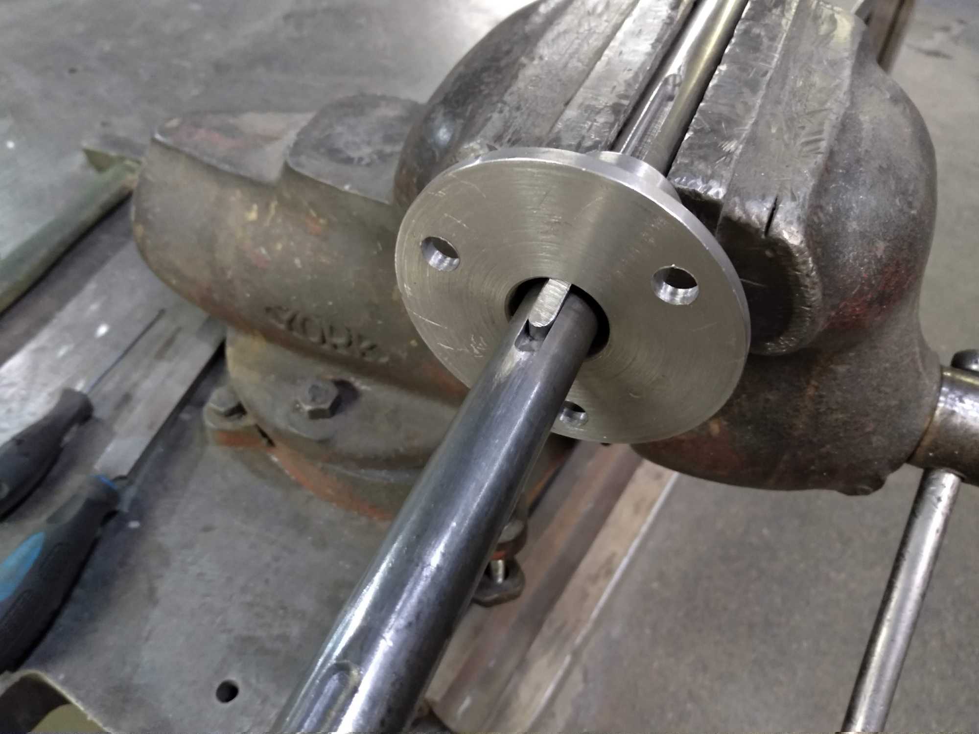
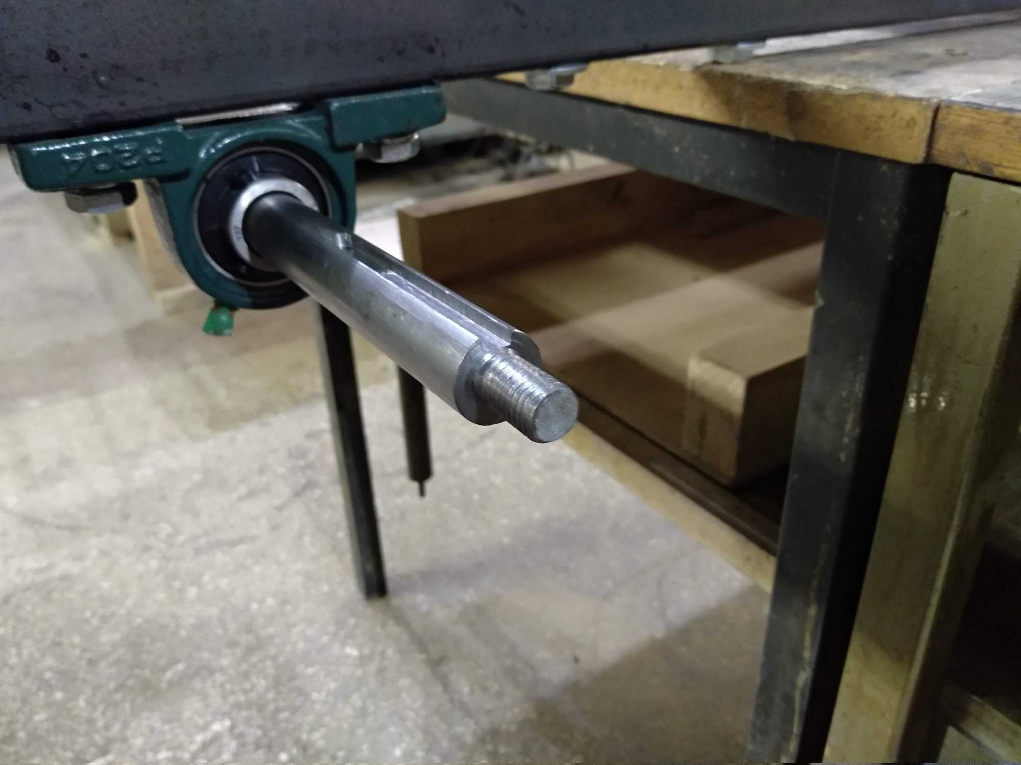
Also for the wheel shaft I used a 20mm steel rod which I had milled to have those grooves to lock stuff in place and that way I can disassemble everything if needed.
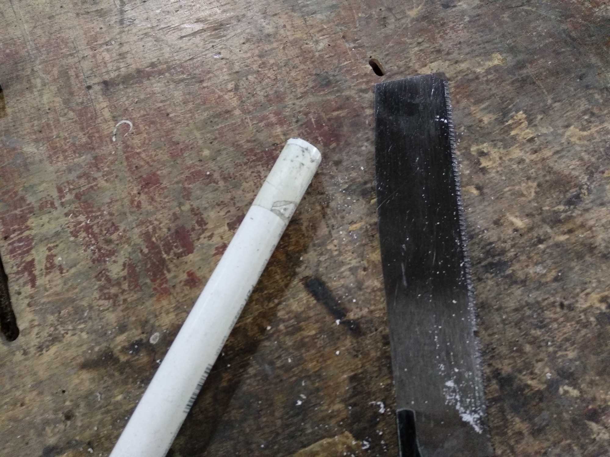
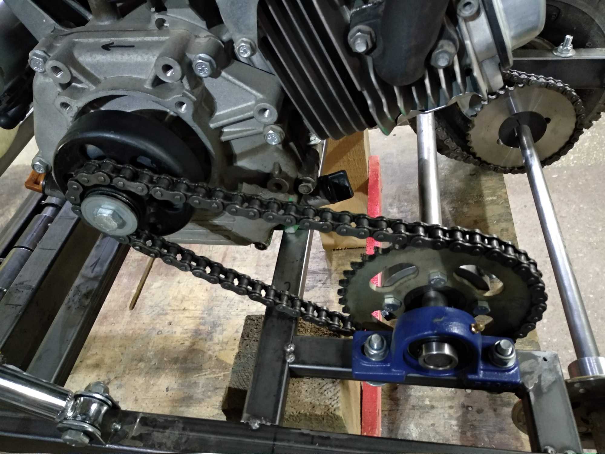
Next I mounted the rear wheels and connected the chain. For bushings between the wheels I used pieces of a PVC pipe.
Then I mounted the engine and connected its chain as well as a gas pedal.
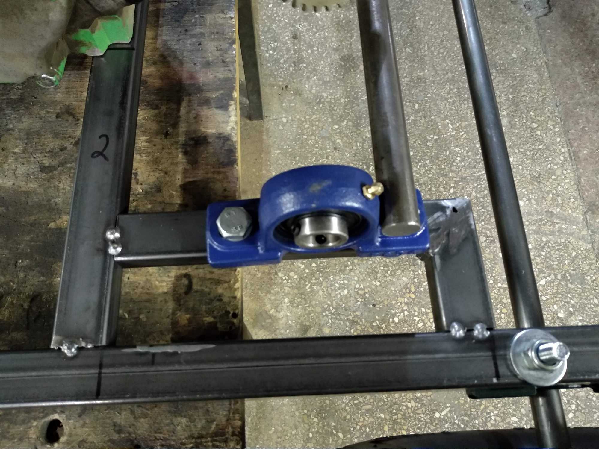
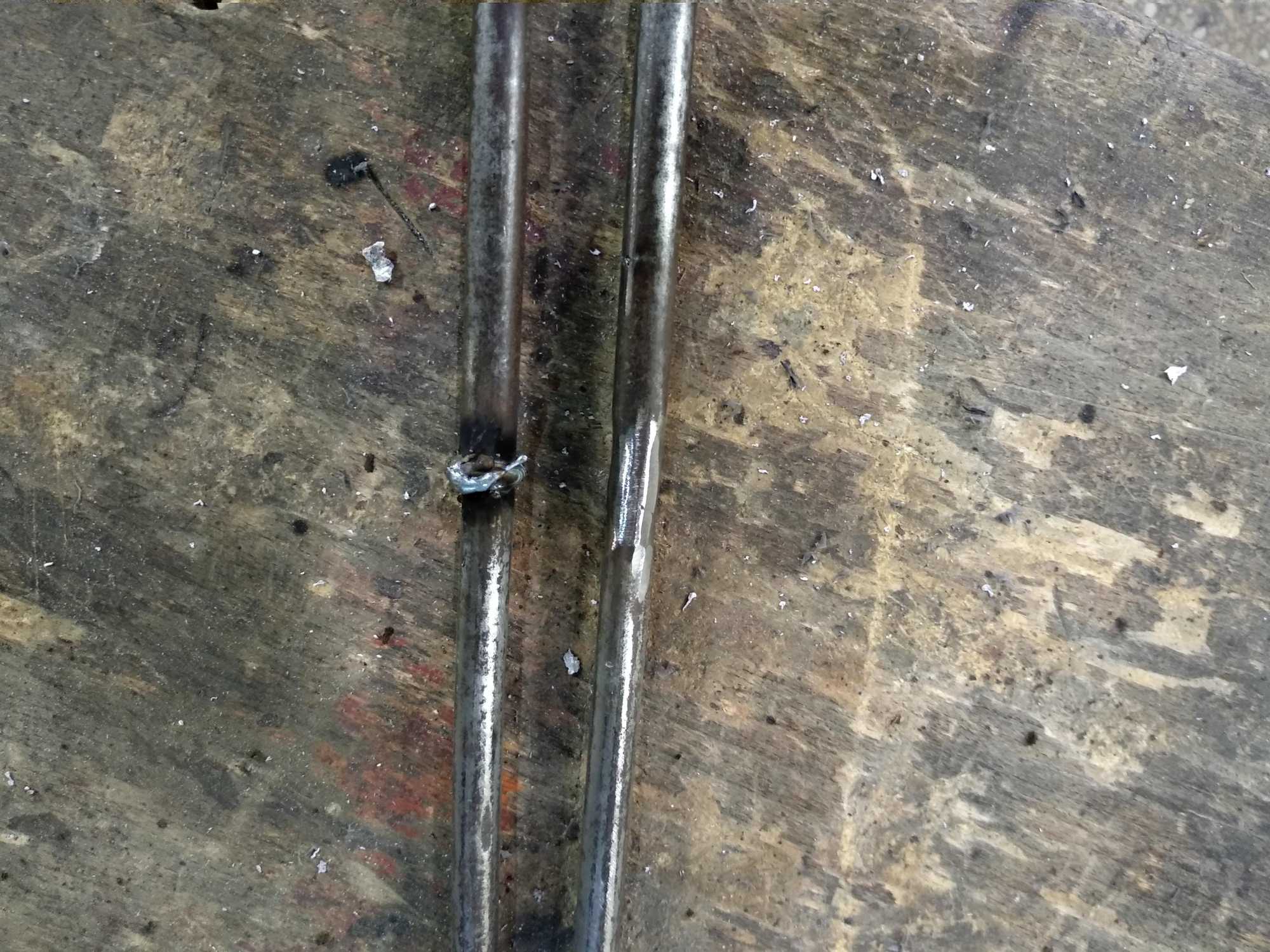
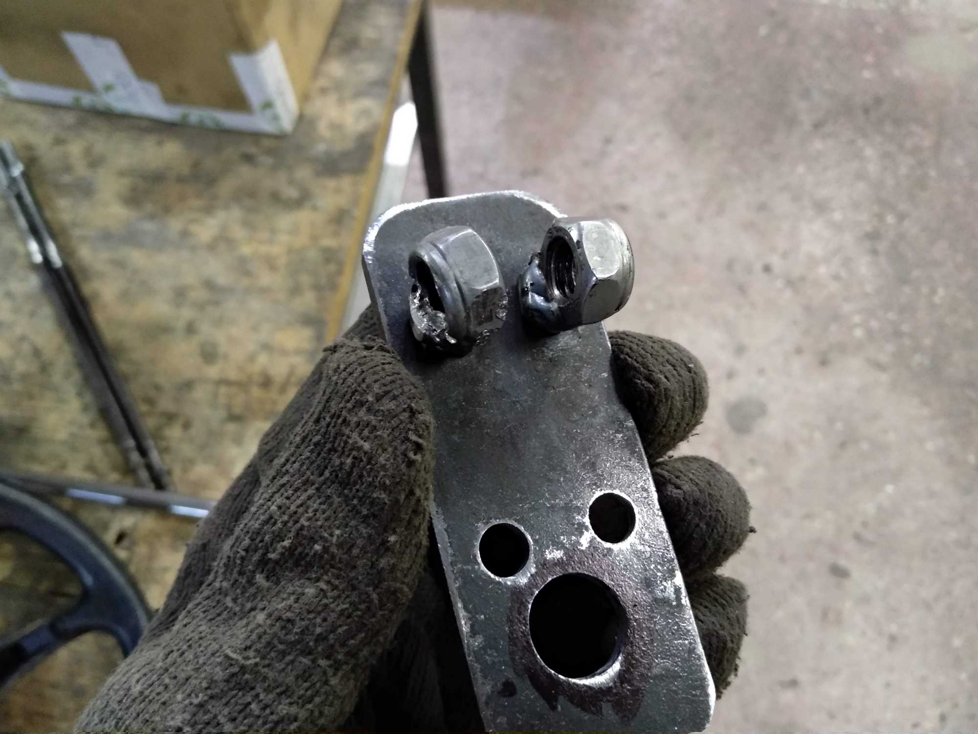
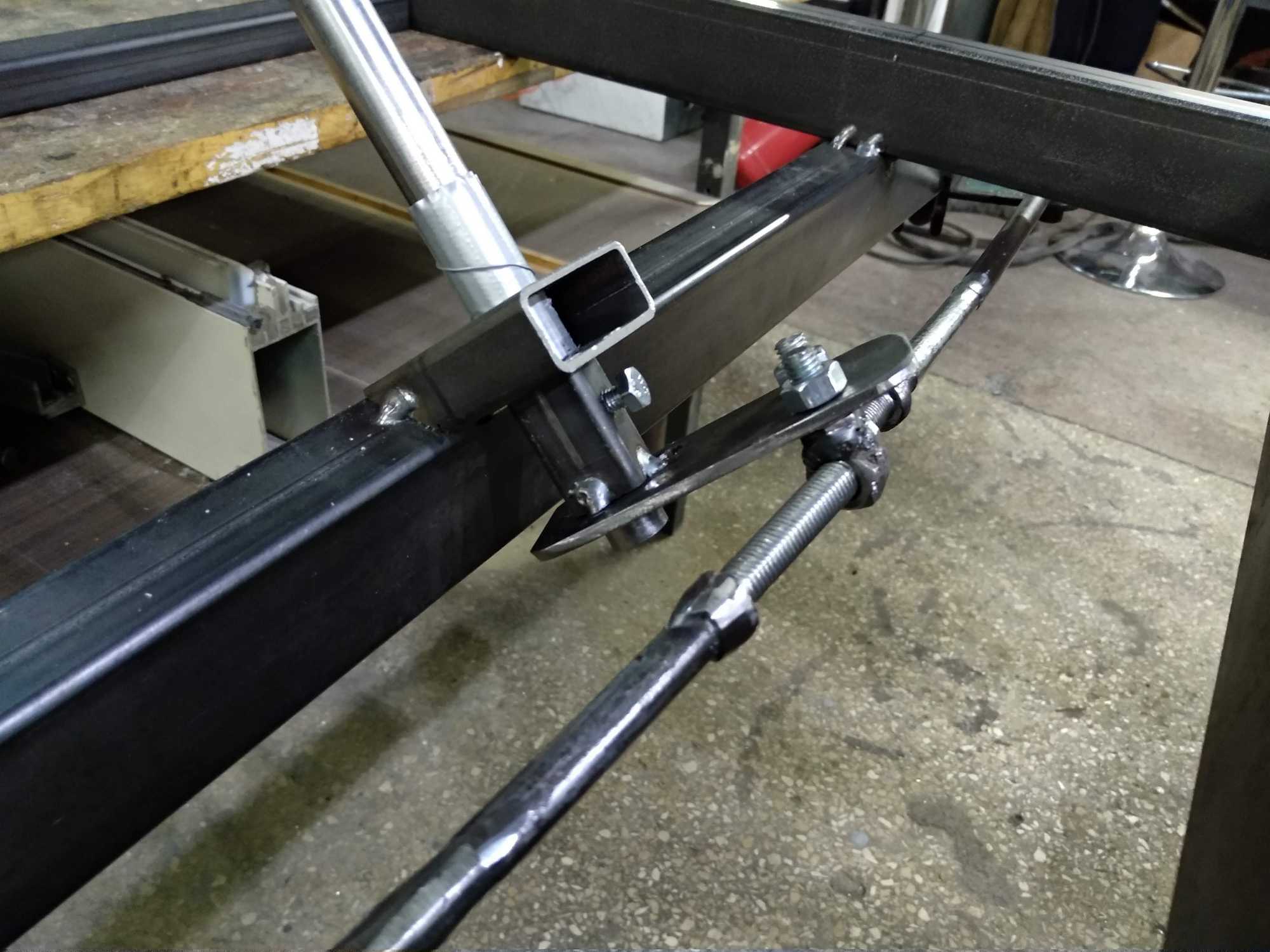
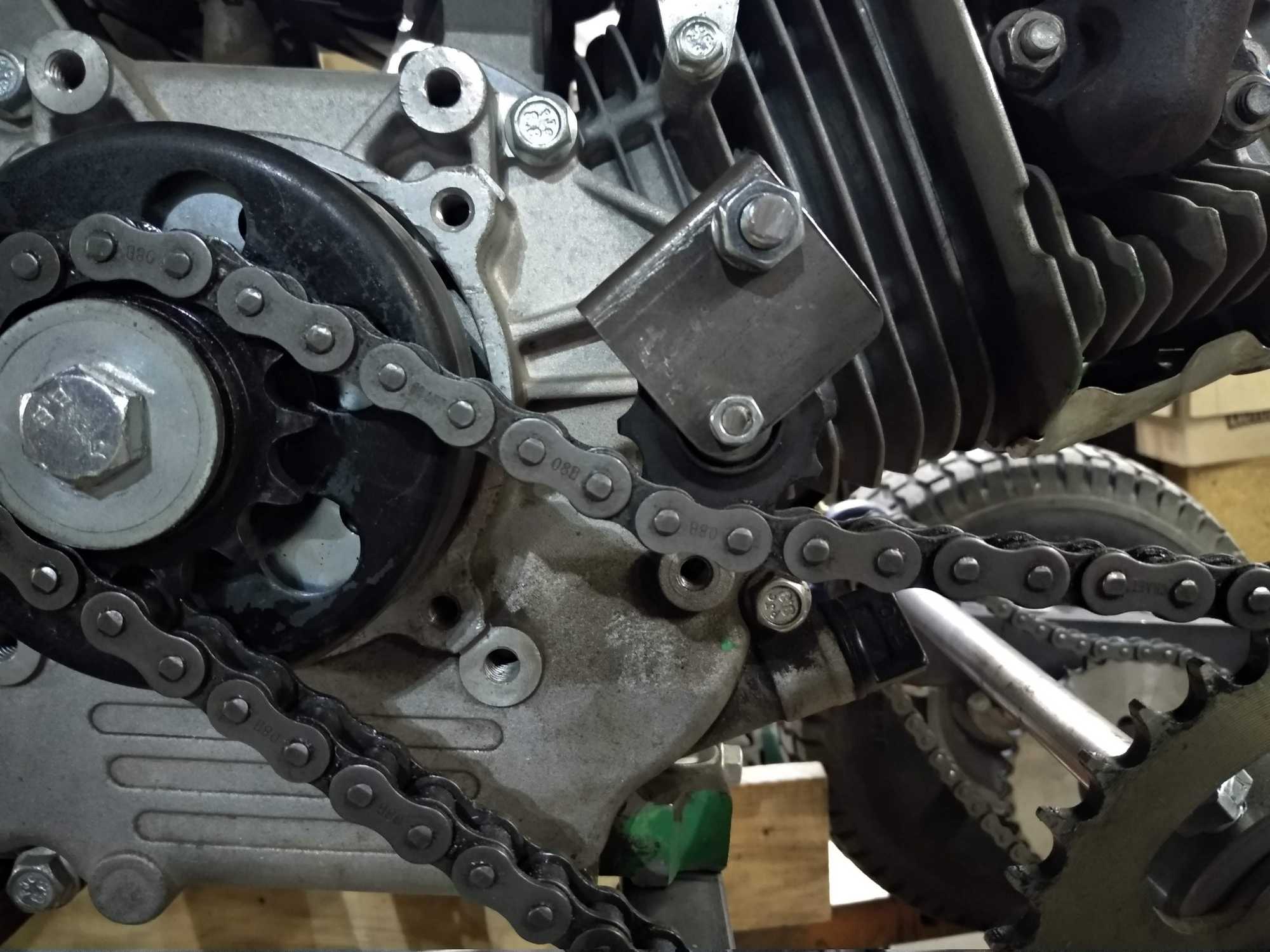
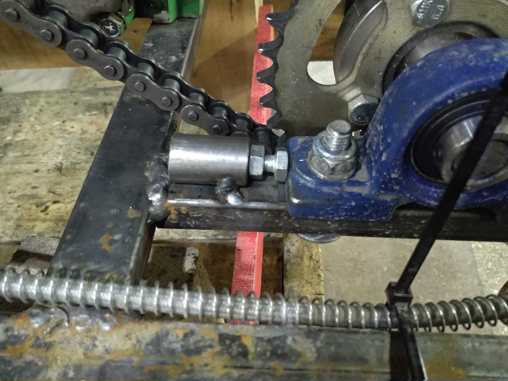
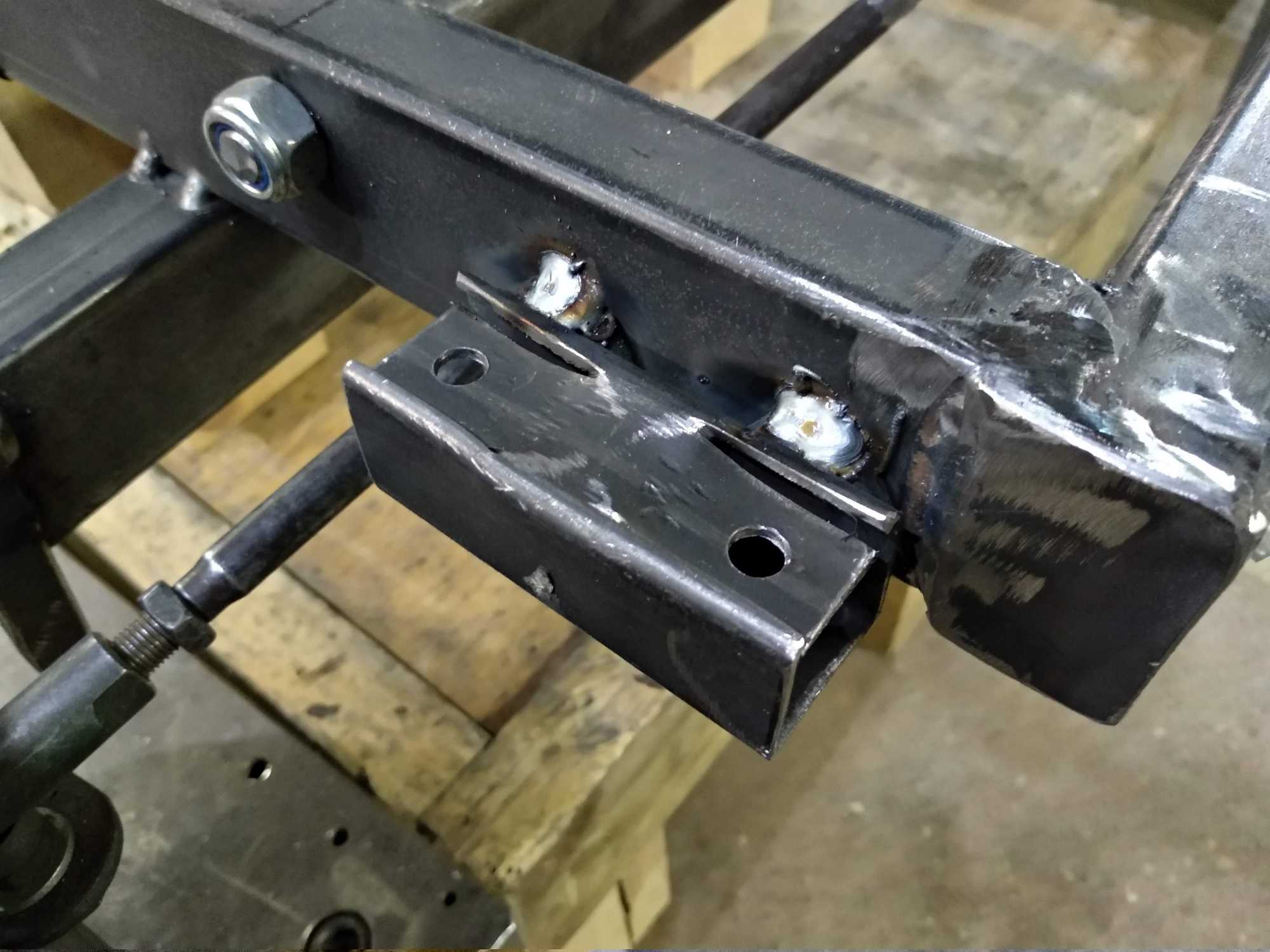
After which I needed to somehow tension the chains, so I came up with this mechanism. The chain type I used were 08B
But that didn’t work at all, because the force of the chain is so big that it bends the whole roller back, also this creates lots of noise, which I don’t like. So after more thinking, I decided to just use bearings to tension the chain, seemed alright.
I also thought that I should add a some kind of “bumper” to the front to deflect stuff from front wheels and to lessen the shock if I happen to hit something. The rubber hose you see there doesn’t do anything, really, it’s to fill a gap. But if I hit a tree hard enough this might bend and absorb a tiny bit of the hit :P also it looks cooler now.
And finally, after test-driving a little bit around the backyard here, I did tier-1 engine mods:
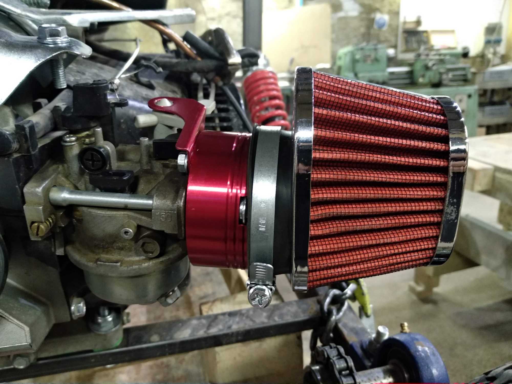
- Replaced a stock air filter with a high-flow air filter from car parts store
- To replace the air filter, I had to order an adapter from AliExpress
- Replaced the main jet to one with a bigger hole – #105 if I remember correct, but later I noticed that it’s not enough when using the high-flow filter – the engine would bog down when I’d step on the gas pedal. I drilled a 1.5mm hole in the main jet and that was perfect.
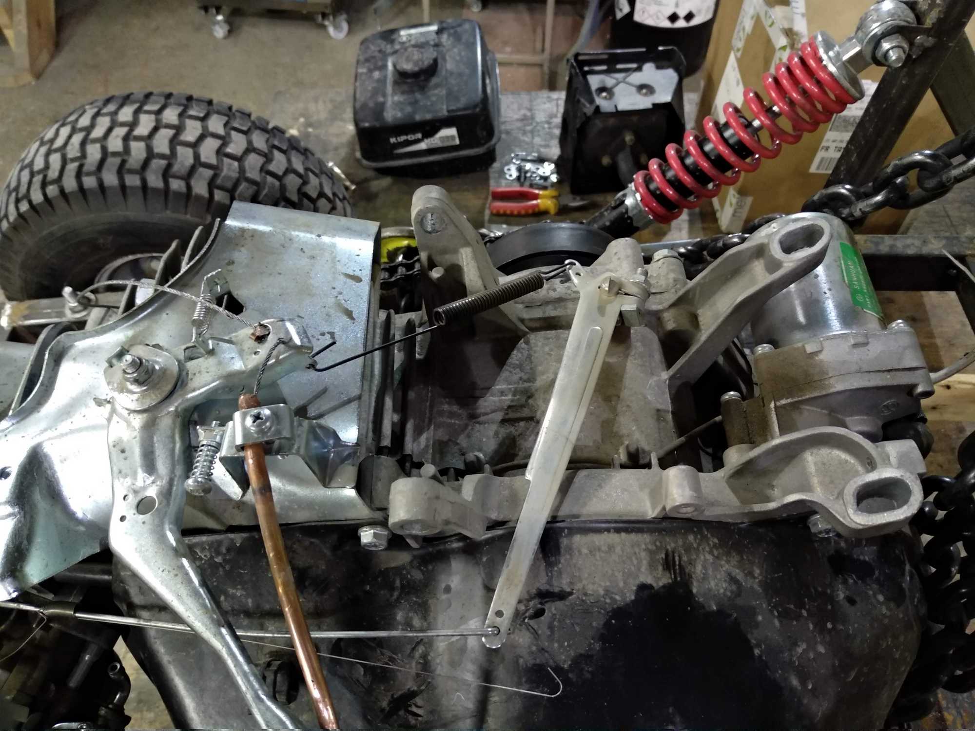
- Disconnected the governor – thankfully this engine allowed me to disconnect the governor so that the arm spins freely and I didn’t need to cut anything or open the engine up to remove it completely. Hopefully this won’t cause any problems.
When disconnecting the governor, I left the whole regulating mechanism in place, but modified it a bit to be independent. This way I can still control the maximum throttle I allow to apply with the pedal. This is really good if I were to bring this to some event for other people to ride it.
And here’s a video of it working with the governor bypassed and high-flow air filter installed:
EDIT 2020.03.03:
After a bit of stress testing while the rear was lifted, the engine broke down a bit.
During the test everything was fine and I left it like that. After a couple of days I tried to start it again and it was completely blocked – I couldn’t turn the crank. A bit of jerking the crankshaft made it loose and I was able to start it again, however though after a minute it began to rattle so hard I thought it’ll explode. It was at this moment that I knew – I dun fucked up.
At first I thought that the connecting rod might of broke, because if it did, I’d have to replace it and that would be a major problem just because Kipor doesn’t/didn’t make any spare parts for this particular engine, it seems. Replacing with an alternative (if there was any) would cost me half the engine price if not more.
But after opening it I noticed that the connecting rod bolts had become loose and was on the edge of falling out – almost got caught inside the gears, that would of destroyed the engine from inside and then I could only scrap it…
The repair here is pretty simple – just to screw it back on and use threadlocker to keep it in place. But of course it can’t be that simple. After removing the lower part of the connecting rod I noticed a weird thing – it doesn’t have any rod bearings. The engine was developed not to have any and that is very bad for my use case and pretty bad for normal use in the long run. That means that the connecting rod always rubs against the crankshaft directly and on the bottom of the engine there were a looooot of aluminum shavings from the connecting rod. Obviously after some amount of hours this engine will wear off so much that it will get stuck and blow up, looks like planned obsolescence if you ask me.
Somehow I expected a bit more from this kinda engine, even though it’s a cheap chinese one, but still costs a lot.
When put together the crankshaft was still a bit loose. Looked like it was deformed a little. Had to use a file to make it fit properly, but then it was too tight, but still turning.
Since I got it open I completely removed the governor as well, since I won’t be using it. I didn’t want to have it spinning for nothing. Might become a problem later.
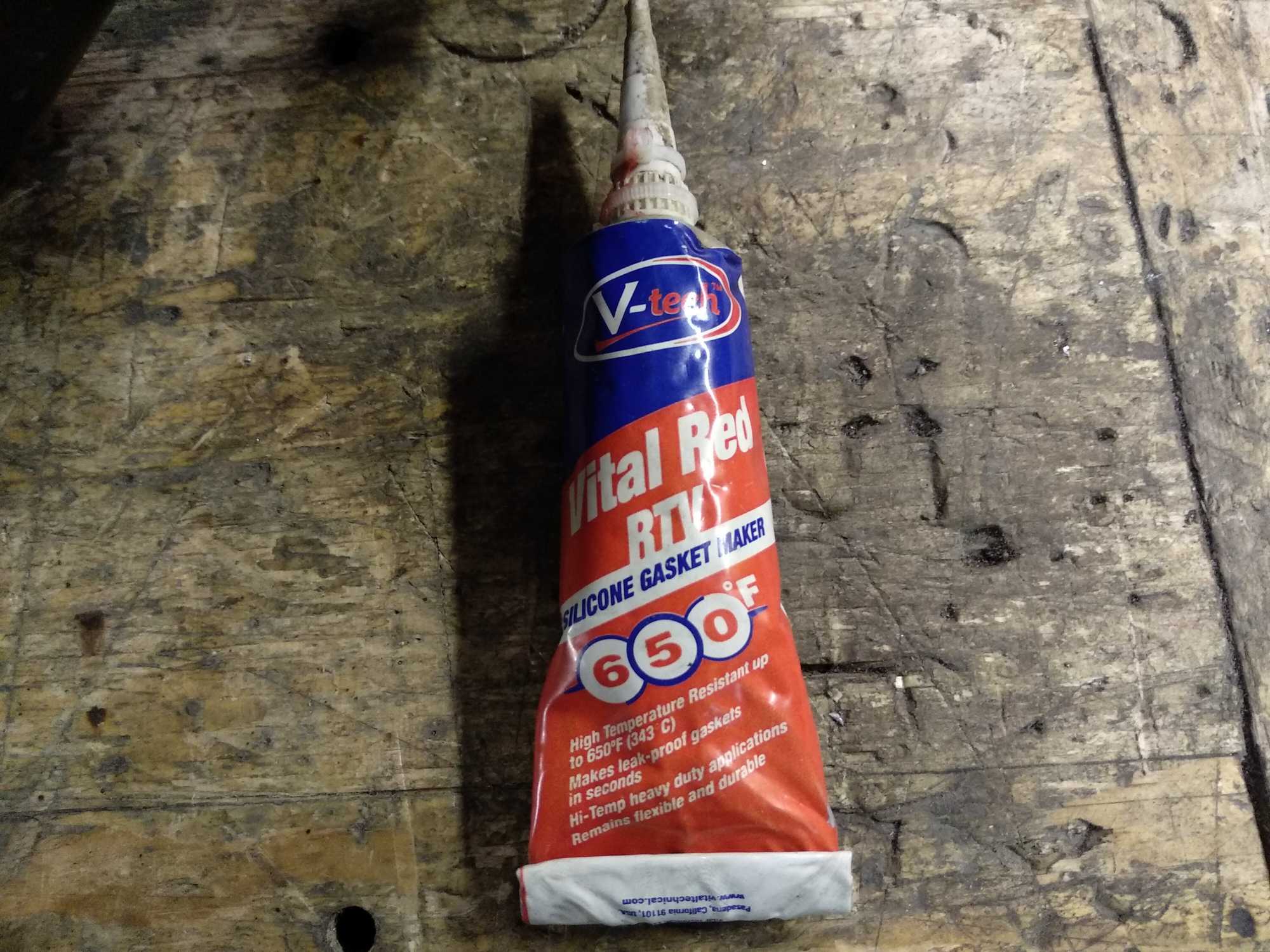
And when all that was done, I sealed it back up using a silicone gasket maker and let it dry before trying to start it up again. If it does, it’ll need to stay in idle for a while to make way for the connecting rod.
This is it for part 1. I’ll update this article with insights and videos whenever I’ll test this contraption on a field. It’s rainy season now and it looks like it’ll be here for a while. Might be another month or two until it’s dry enough to ride. Otherwise the wheels splash dirt all around and that’s not cool.


