
So some time ago I was asked to make this apparatus – a (flash?) light with intensity controlled remotely. The idea was that it could be hanged in some place and aimed at what needed to be illuminated and after that you should be able to remote-control the light intensity.
The light source (doesn’t need to be very bright) must be able to have enough power to last for at least a week sitting in idle (only listening to radio signals) and a few hours of constant illumination at night. Depending on the darkness of the night the light source intensity could be adjusted. However the distances over which it would be controlled are 200-300m.
The whole receiving and lighting part needs to be modular – battery, controller and light must be separate for easier handling.
This is pretty easy, fun and a straight-forward task to do with arduinos, but the radio modulation presented a challenge, since it’s the first time I have touched these and SPI as well.
Turns out that there aren’t many solutions to this. There exists a few radio modulators, but they all go up to 100m at best AFAIK. However there is one – LoRa and that’s what I used.
Reading different sources I could gather that a normal distance for LoRa is a few kilometers and that’s what it was designed for. The distance you could reach obviously depends on the environment you’re in, the equipment you use (antennas, power source) and the settings you set for modulators.
LoRa is able to reach such distances with the cost of transfer speed. Meaning it’s ideal to send some sensor values from time to time and not for something that needs to pass a lot of data or pass that data very fast.
So I got to know all the requirements and started to sketch out ideas of how I might construct this.
The beginning
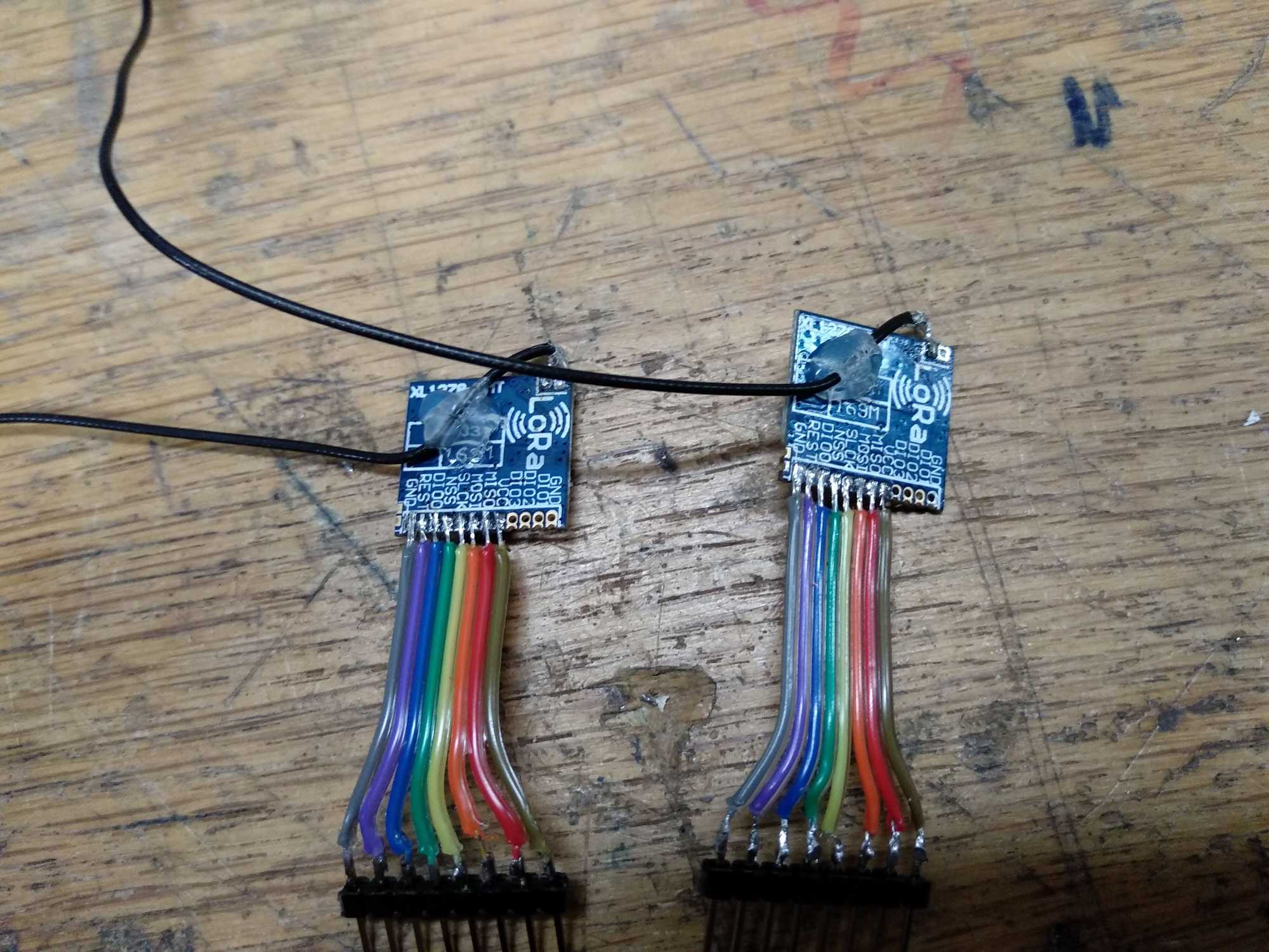
For starters I ordered two Arduino Nano boards together with LoRa modulators, bought some patch wires, a pot(entiometer) and an LED to see how that would even work. The modulators I bought were very tiny, perfect for my project, but with that came non-standard, very tiny, contact steps which was a bit challenging to solder a ribbon cable to but eventually I had that done, it was also very easy to hook them up to arduinos as it turns out.


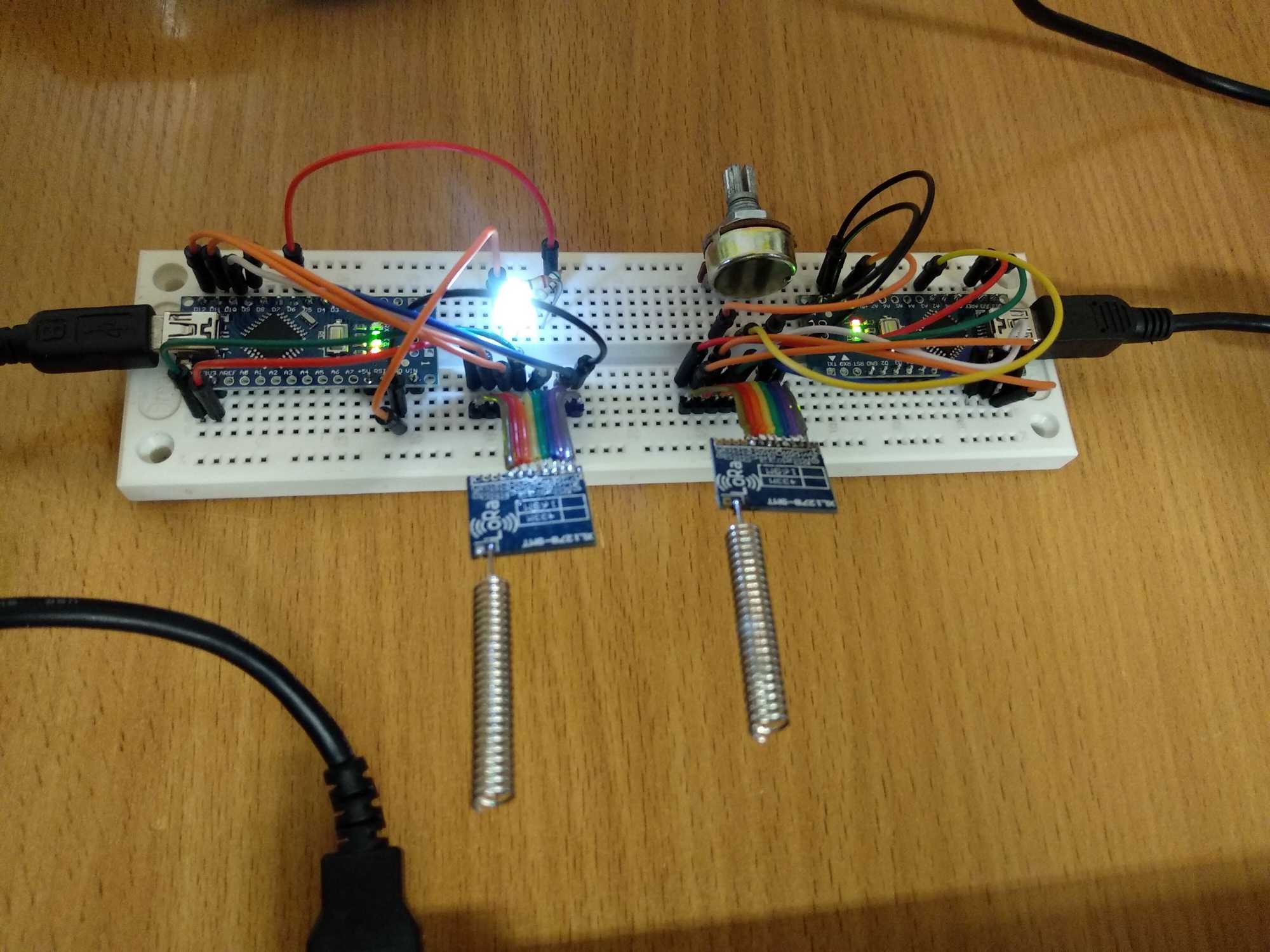


The antenna should connect to the positive terminal, which is the contact on the right of those two.
The contacts that are used for LoRa’s SPI communication are REST, NSS, SLCK, MOSI, MISO and then ofcourse GND and VCC (3.3v). All these connect to appropriate pins on the nano.
If one end is just for receiving, it could be put into receive mode but then you’d need to connect one additional LoRa’s pin DI00 to nano’s interrupt-capable pin. That way a callback would be fired when it’d receive something.
After connecting the patch wires it worked just like that. And then a few problems came up. First thing was that nano would hang while sending data from time to time. This would happen when you’d send data too fast – I was turning the pot and reading its value without any delays and that’s what caused LoRa to stop responding and the call being not asynchronous, would block further execution. So adding a delay of about 70ms is enough, but it would still hang.
Reading the documentation I saw that LoRa needs at least 120mA of current and nano can’t provide that much through its 3.3v pin. For testing purposes, I was able to mostly solve this by setting the Tx power to the lowest possible with LoRa.setTxPower(txPower);
Once I confirmed that these two work as I’d need them to over short distances, I went ahead and separated these to test the distance, if I could get what I needed.

Having these stock antennas on modulators and having set the lowest Tx power and leaving other settings untouched, I was able to get ~190m keeping a clear line-of-sight. This was really promising.
With better 433MHz antennas and different settings I was able to reach nearly 300m and I stopped experimenting after that – it’s plenty of distance for this project. All testing was done in an urban are between buildings, so there should be a lot of interference. Later I tested them farther from the city in an open field, where the sender was on very high ground and I walked away and I was able to reach 800m keeping a clear line of sight.
The settings I used with this module were:
LoRa.setSignalBandwidth(250E3);
LoRa.setCodingRate4(5);
LoRa.setSpreadingFactor(9);
I tried to use various combinations according to Waspmote’s documentation which is very well written: waspmote_lora_868mhz_915mhz_sx1272_networking_guide.pdf
It’s a bit of a pain to experiment, because some settings are dependent on one another, then I’d have to upload same settings to both arduinos as well…
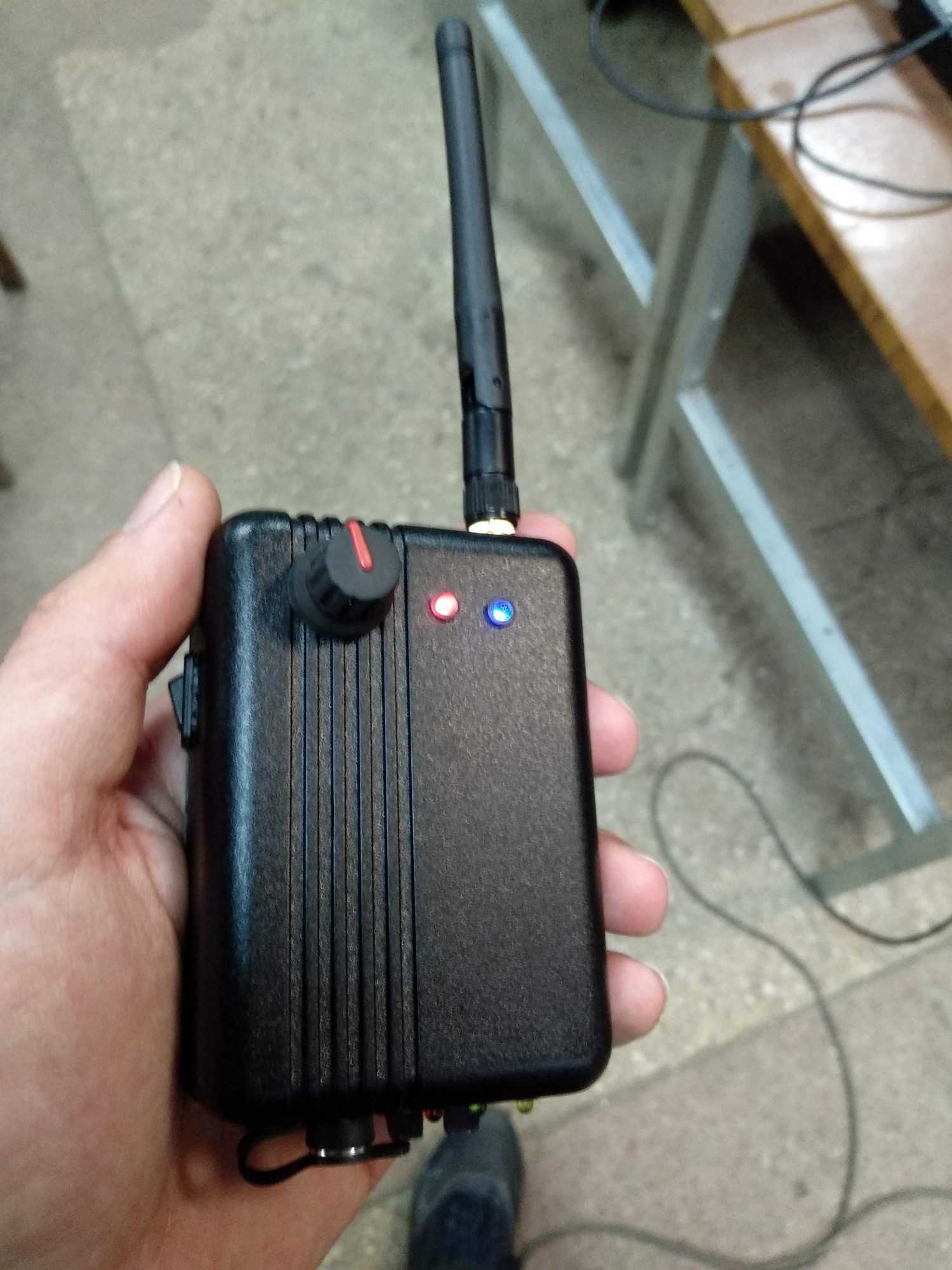
Transmitter
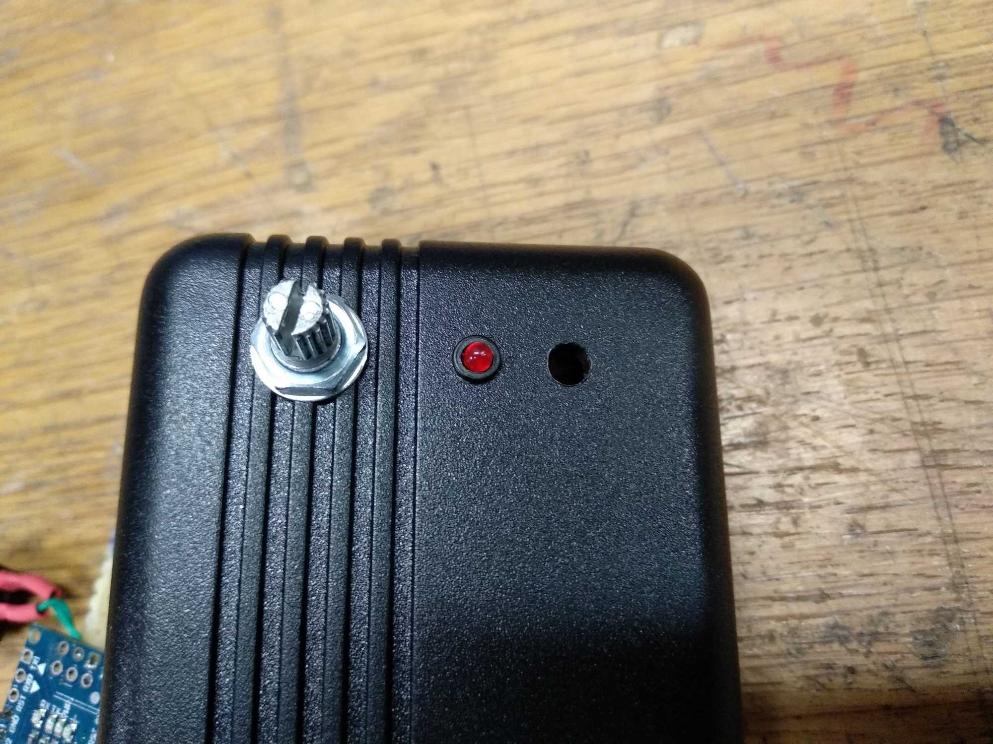
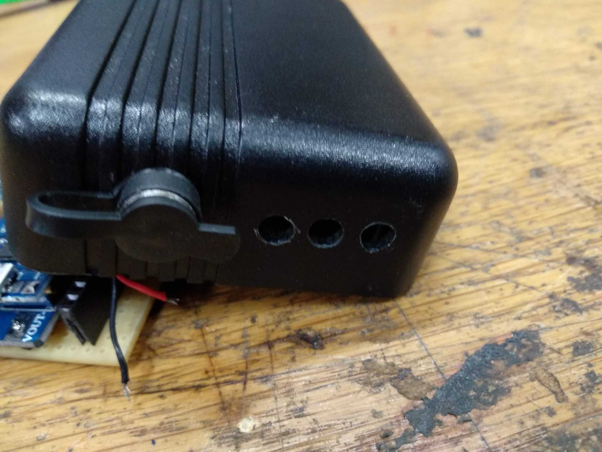
To start assembling everything I decided to first make a transmitter. I planned it to have a potentiometer, obviously, a rocker switch, water-proof DC socket, and 5 indicator LED’s.
For nano: red LED for status, to show errors (by blinking) and status when it has loaded up and is ready, blue LED for a visual representation of the light intensity and to know if arduino has hanged :P and finally a yellow LED to show the battery status, when it needs recharging.
And for LiPo charger module: red for charging, green for full.
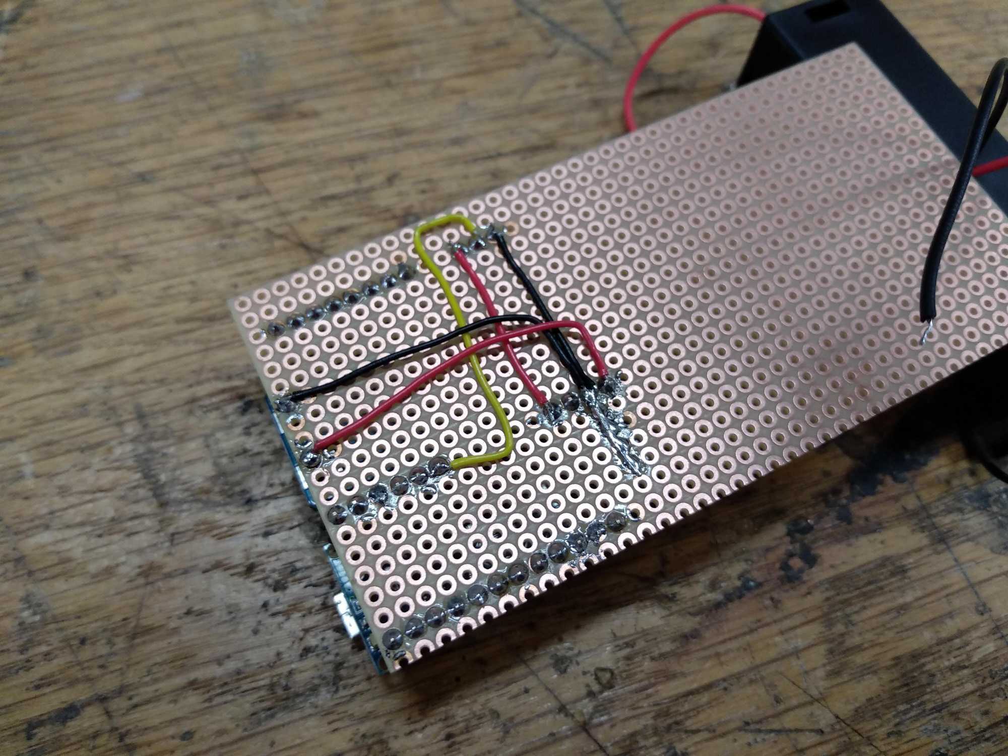
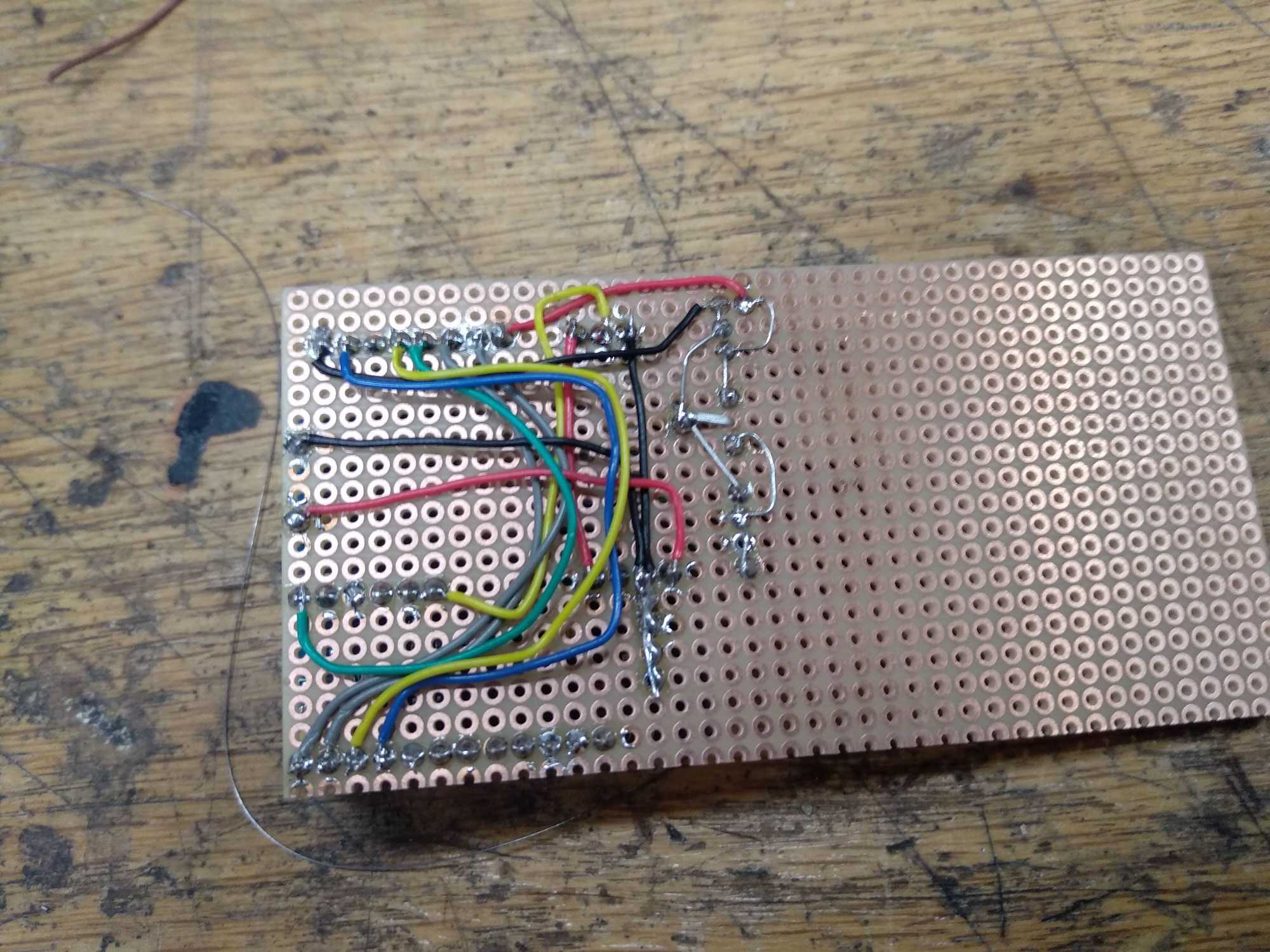
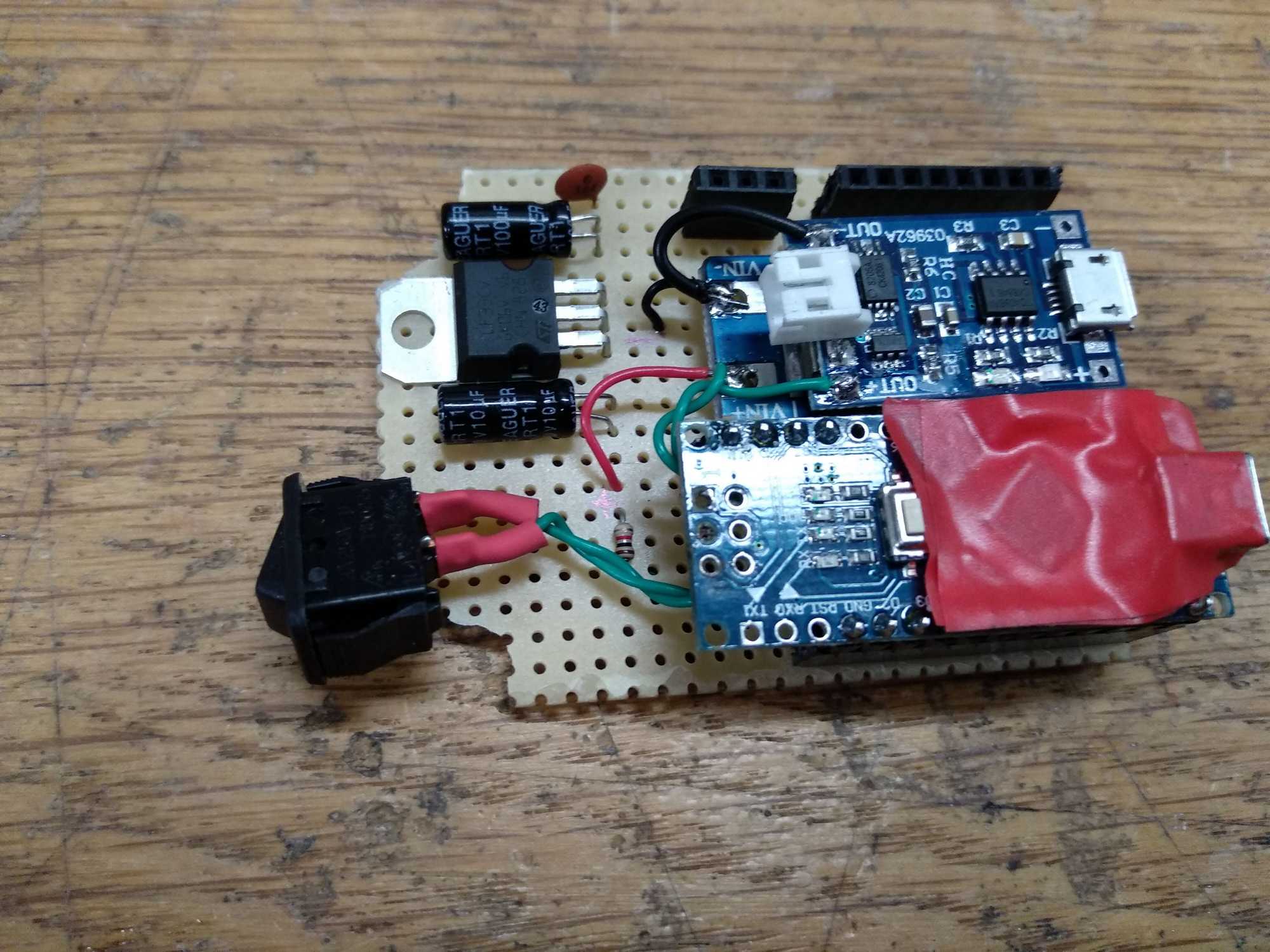
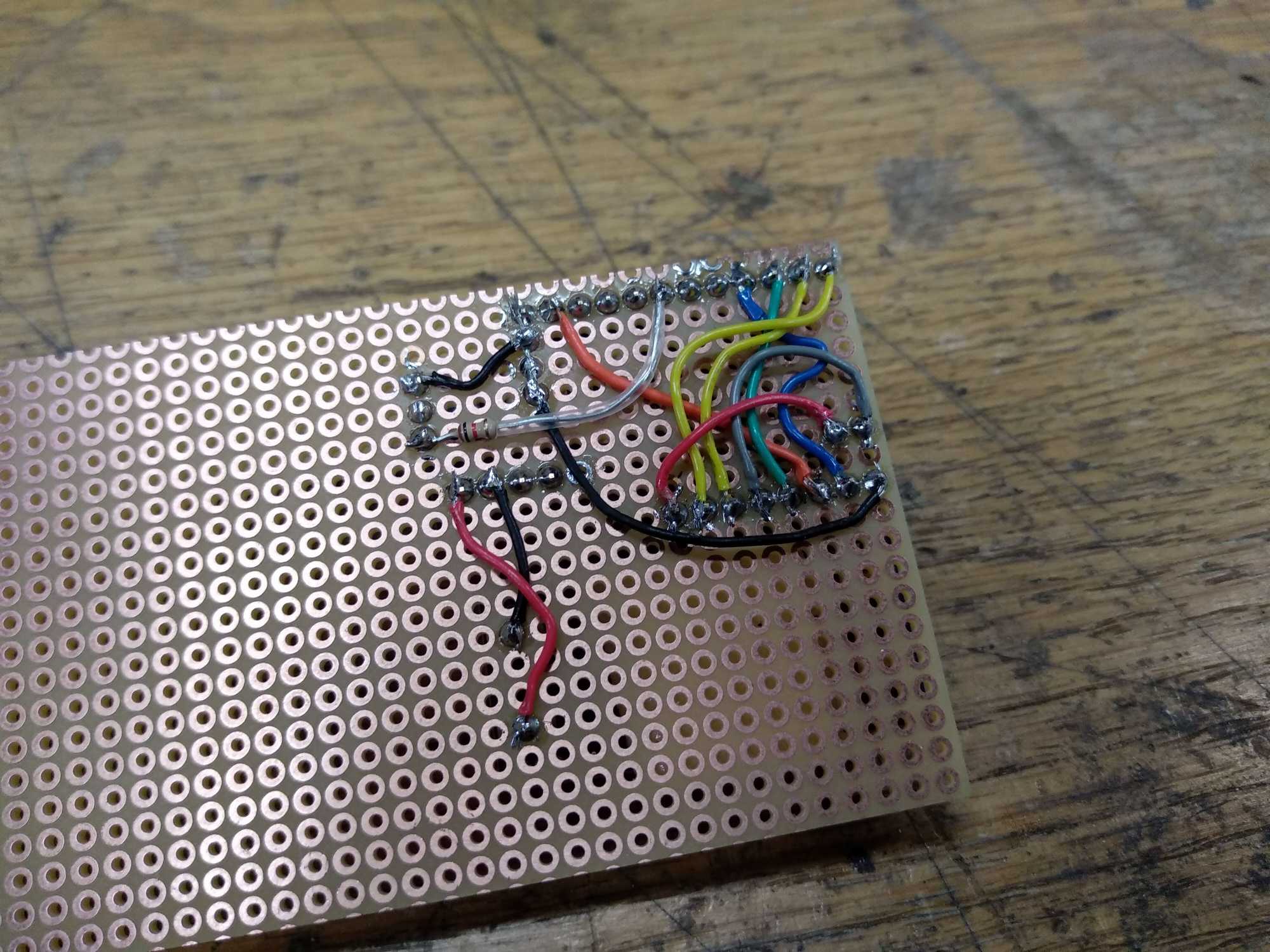
Everything was soldered on a perfboard and connected with wires.
In addition to nano on the board I also used a 1S LiPo charger/manager which has parameters such as:
Charge cut-off voltage: 4.2v +/- 1%
Maximum charging current output: 1000mA
The battery overcharge protection voltage: 4.28v
Battery overcharge lifting voltage: 4.00v
The battery discharge protection voltage: 3.0v
Battery discharge termination voltage: 3.2v
Battery over-current protection current: 3A
So I didn’t use MOSFETs to regulate discharge, but I haven’t tested these features also – I’ll trust that the manufacturer won’t lie in the description :P
I also used a boost converter and a 3.3v voltage regulator LF33CV. It can provide up to 500mA which is more than enough for LoRa.


I was able to read the battery status very easily and reliably. If you use a LiPo cell to power your arduino directly, then you’ll need some stuff, like a voltage divider, to read the status correctly, since this way it messes up with arduino’s ADC.
I was using a boost converter to power the nano on Vin (7v), which was being powered from the LiPo charging module, and so I simply connected the positive of charging module to nano’s analog pin through a 1k resistor and that’s it.
Assembling the transmitter, I wanted to have the final thing as small as possible and also modular – meaning that parts that have most potential to break could be replaceable and to save space I placed everything as close as I could.


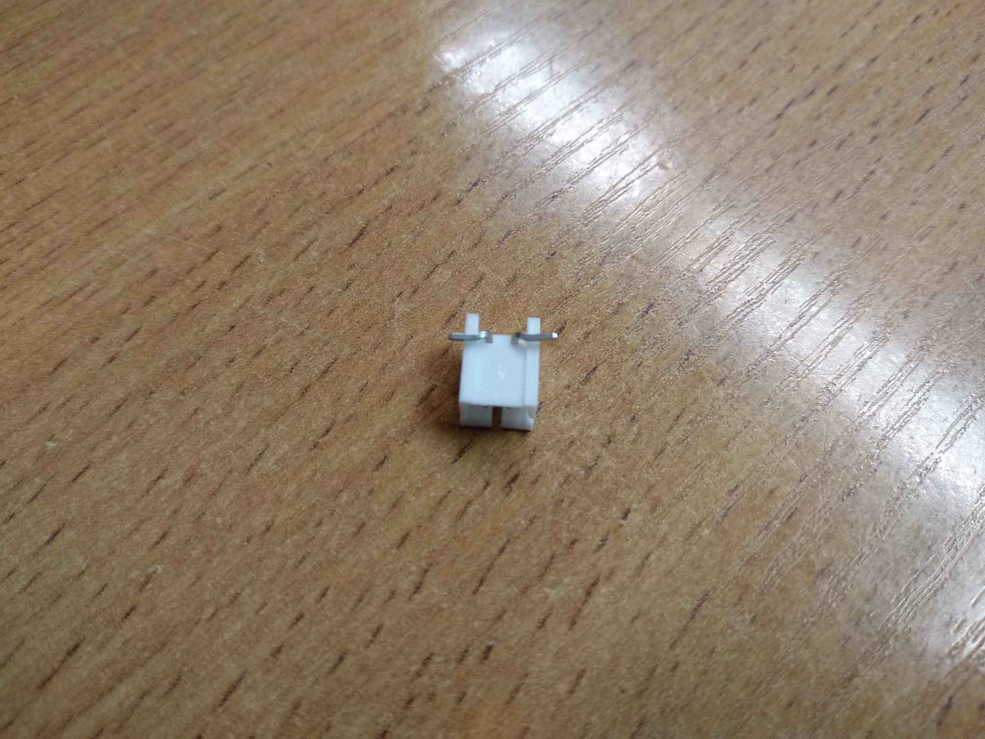


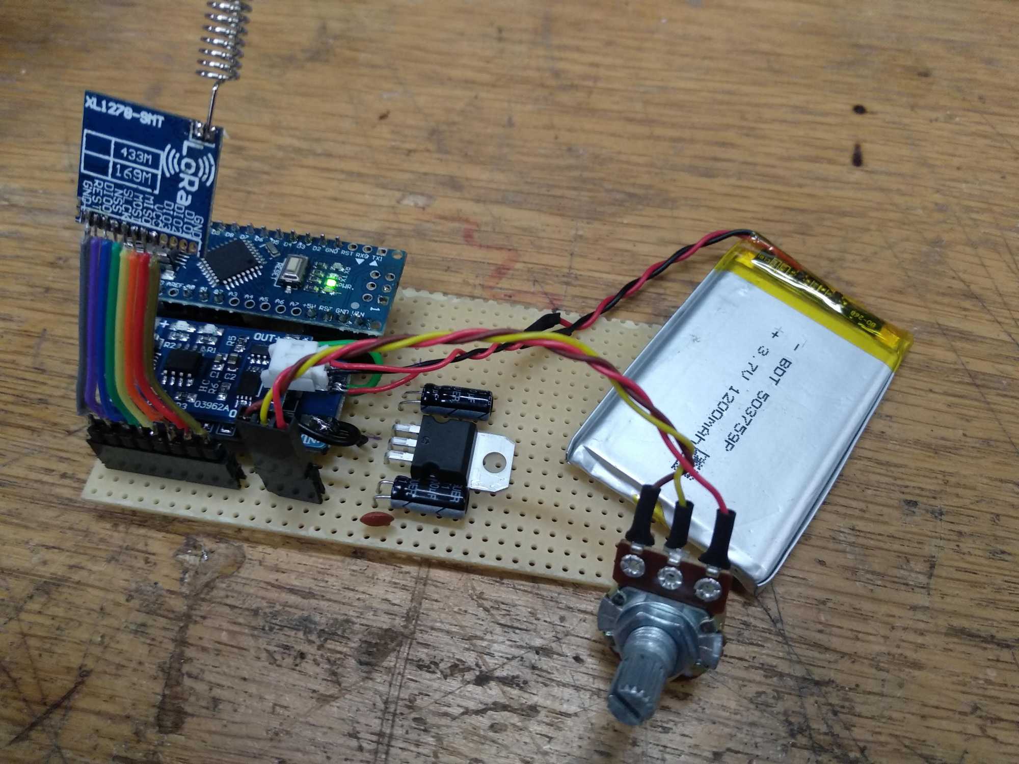
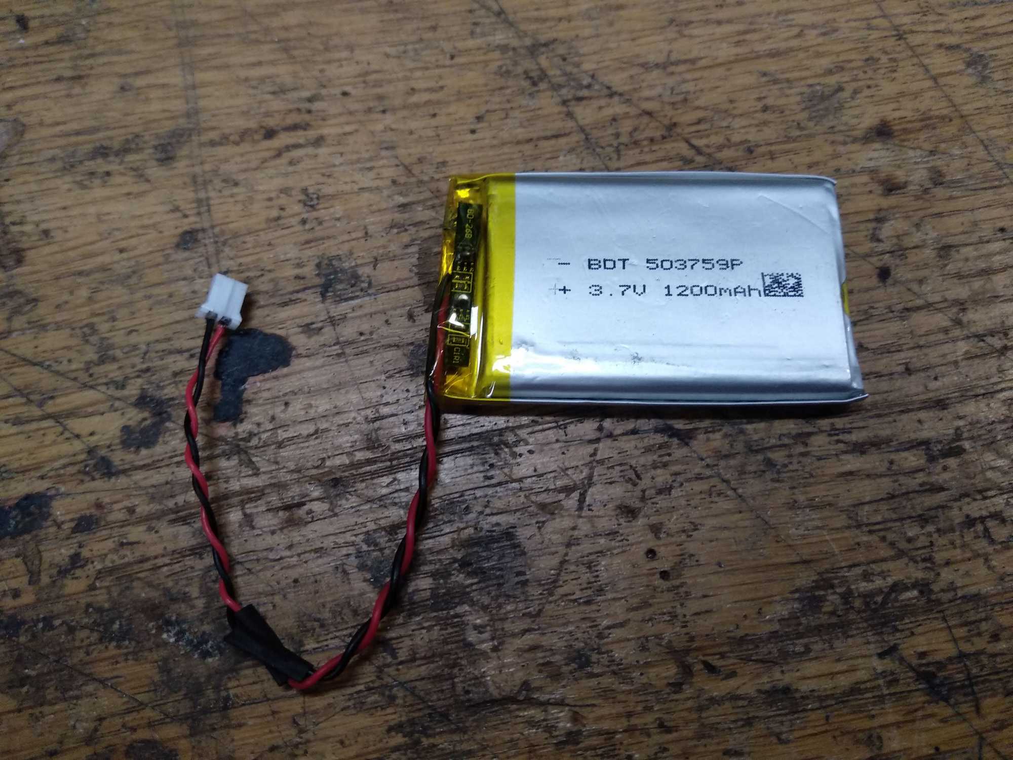
As for the battery, I used a 1200mAh LiPo prismatic cell, also with a connector instead of soldering it.
Originally I also wanted to have U.FL connectors on LoRa modules, but due to ridiculously small contact step-size that was not possible, so I cut the ends of RP-SMA cables and soldered them the old fashioned way :P

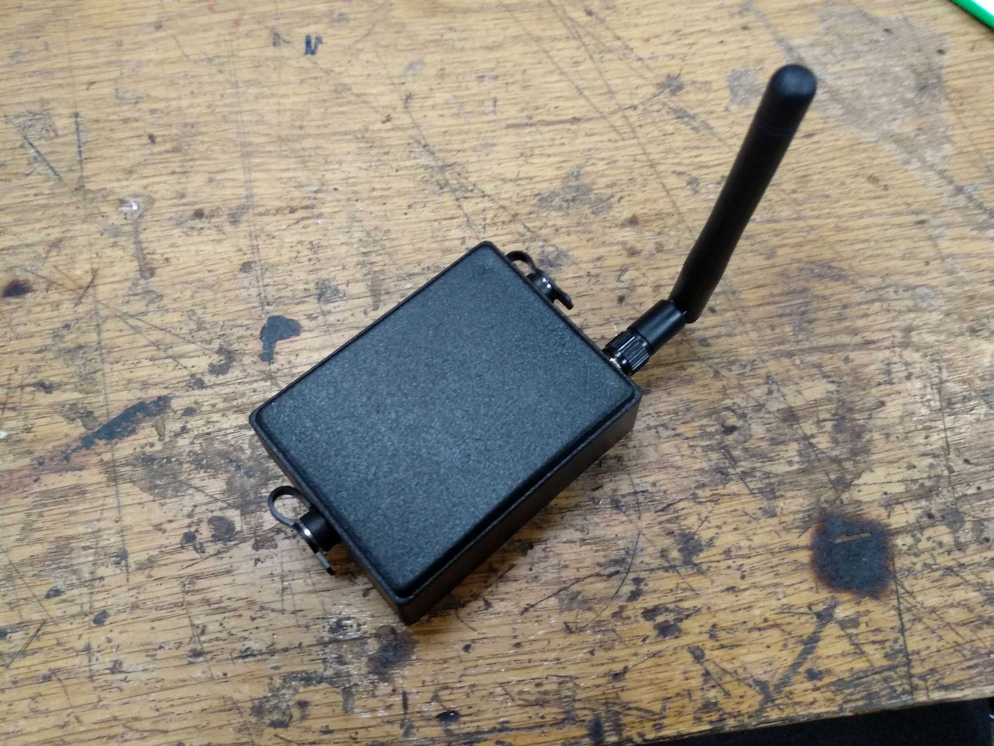
When all that was done, I started assembling everything to a project box.
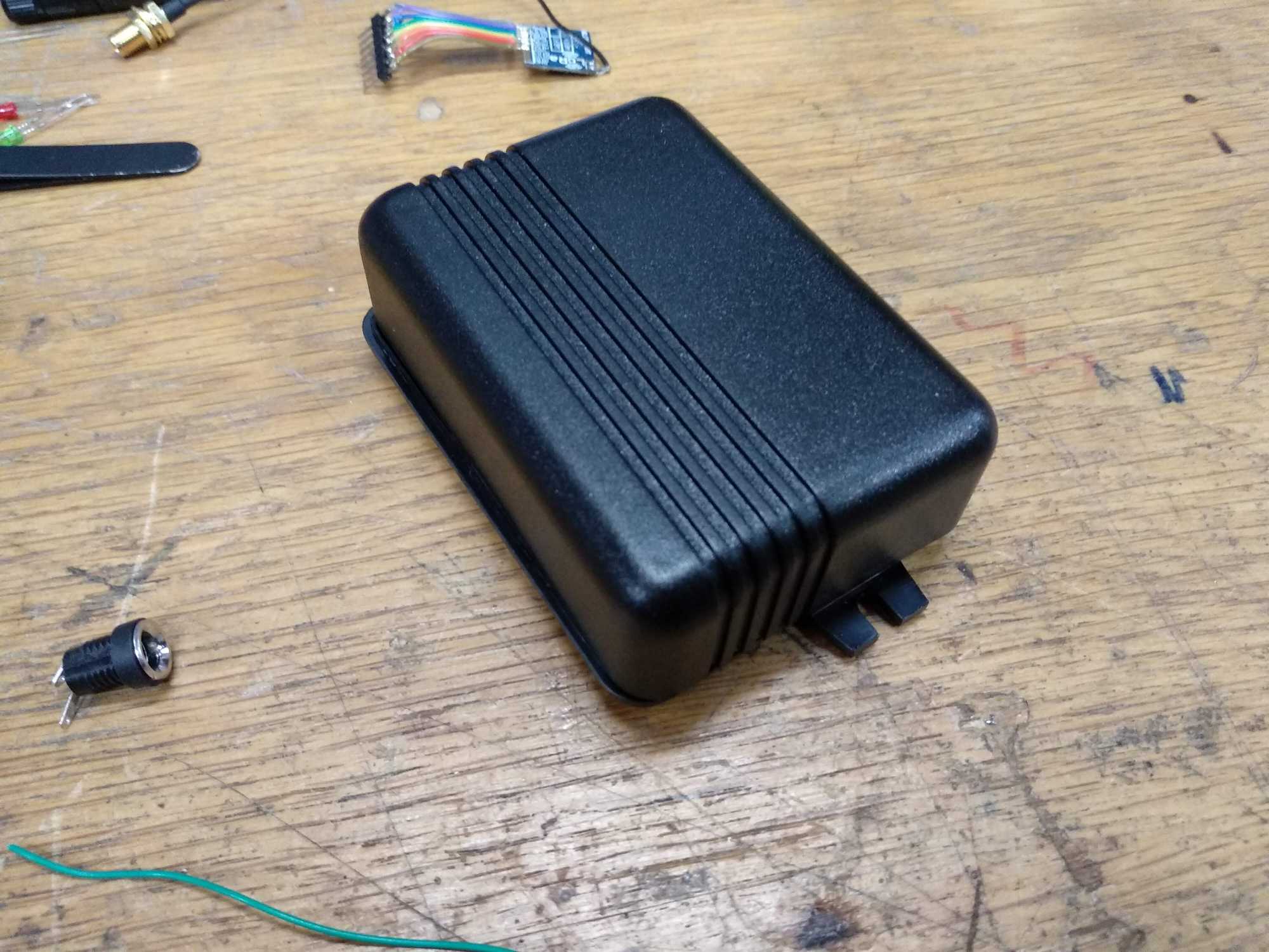


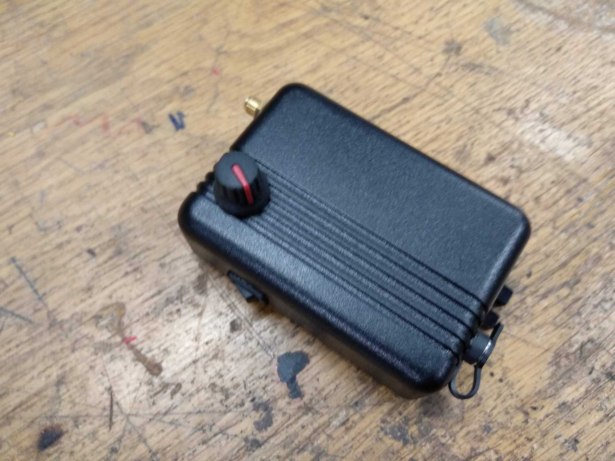


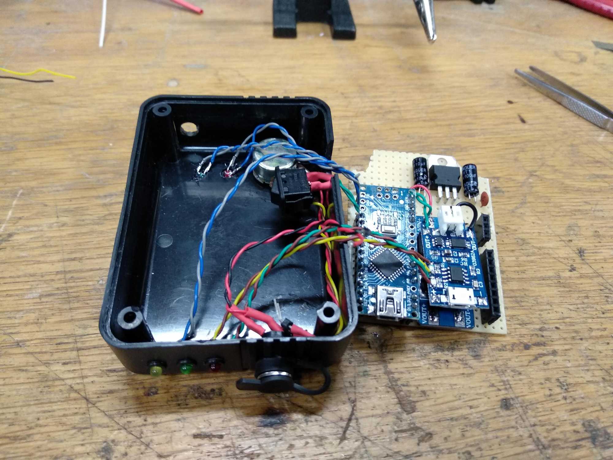
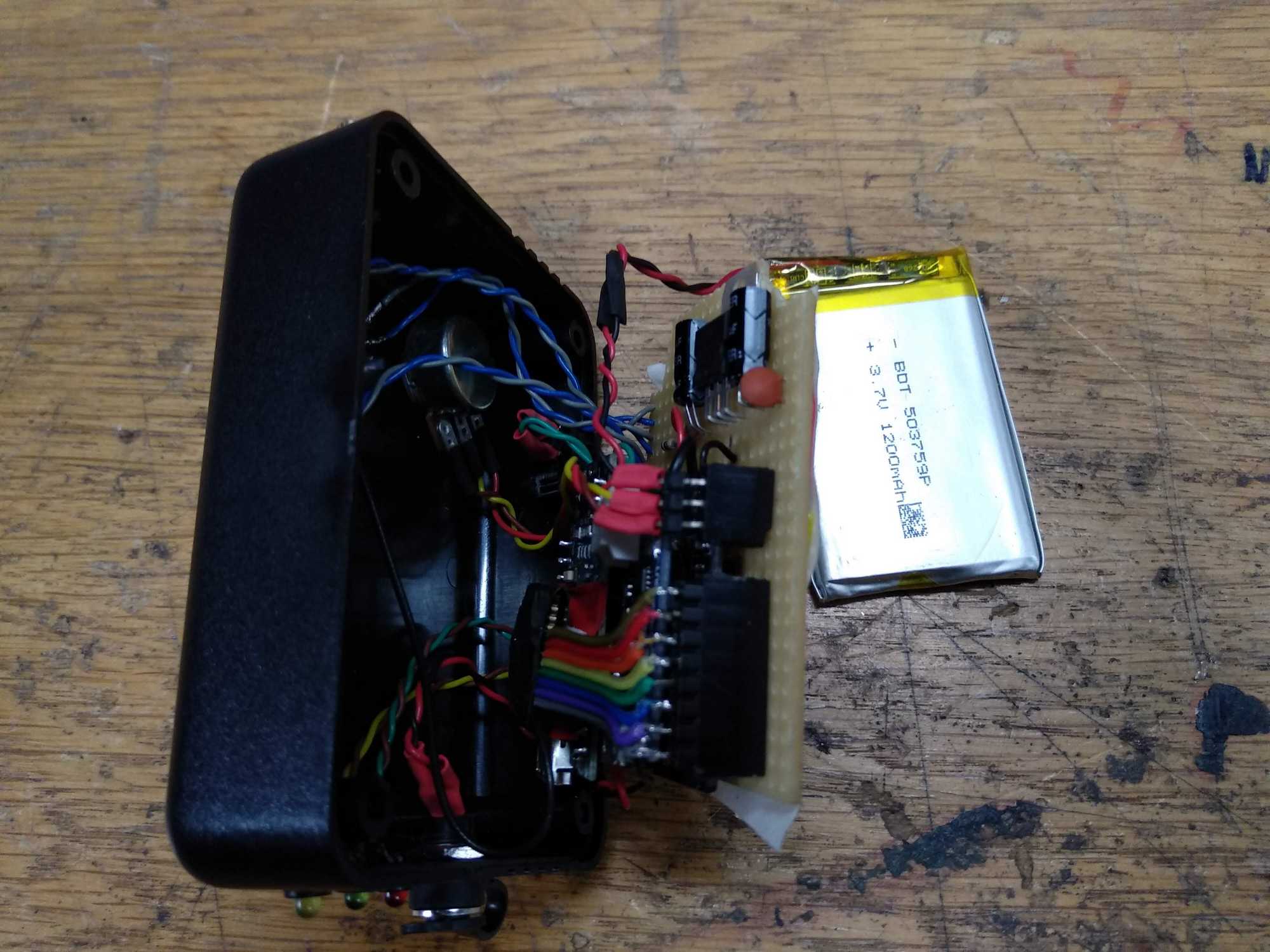
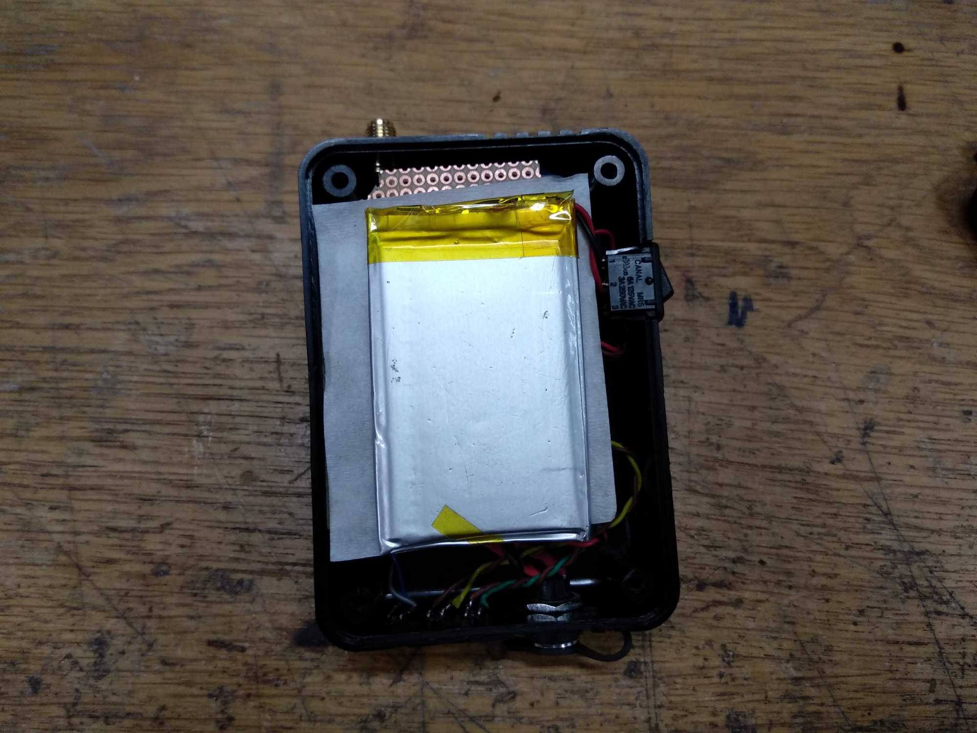
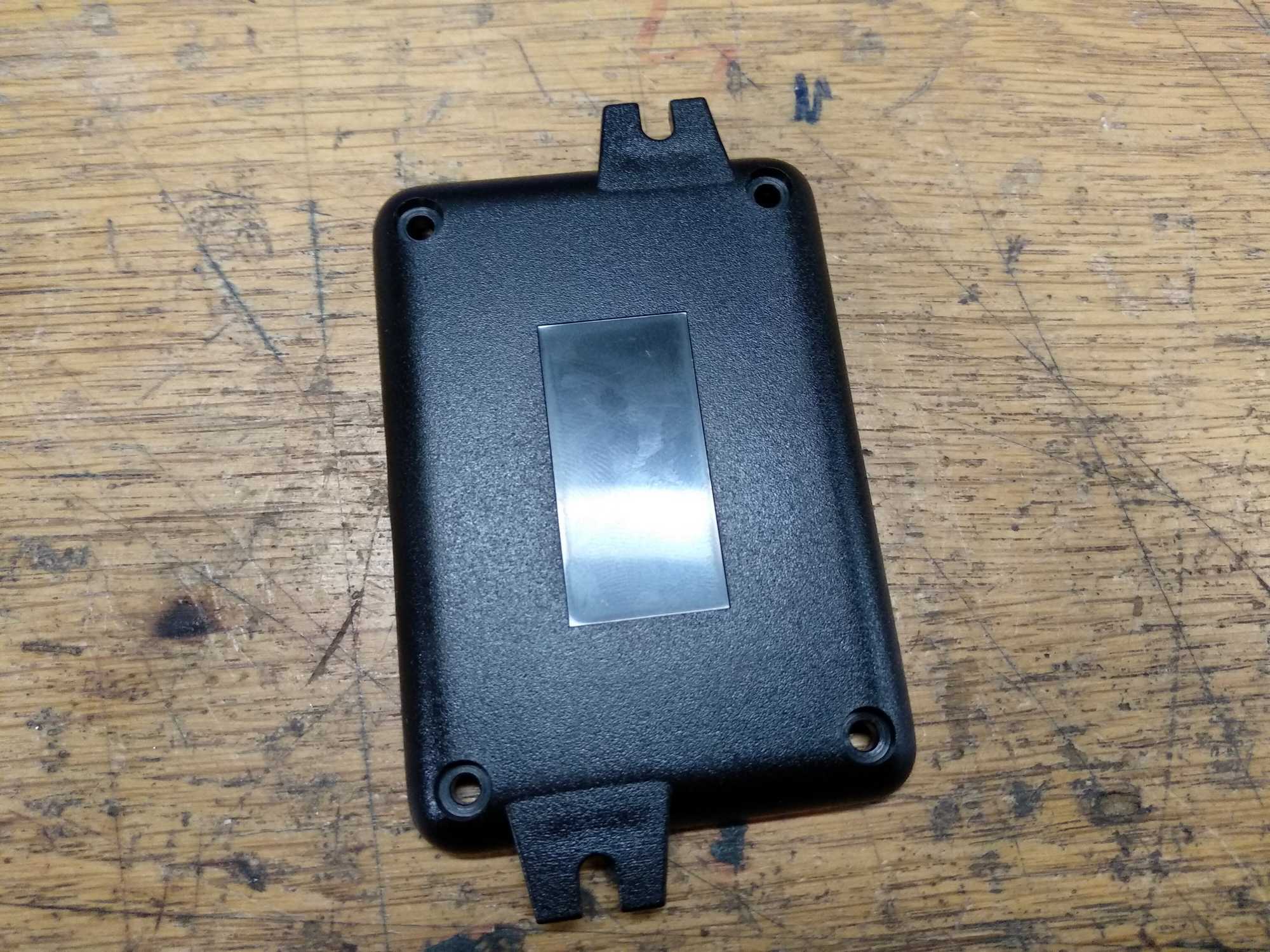
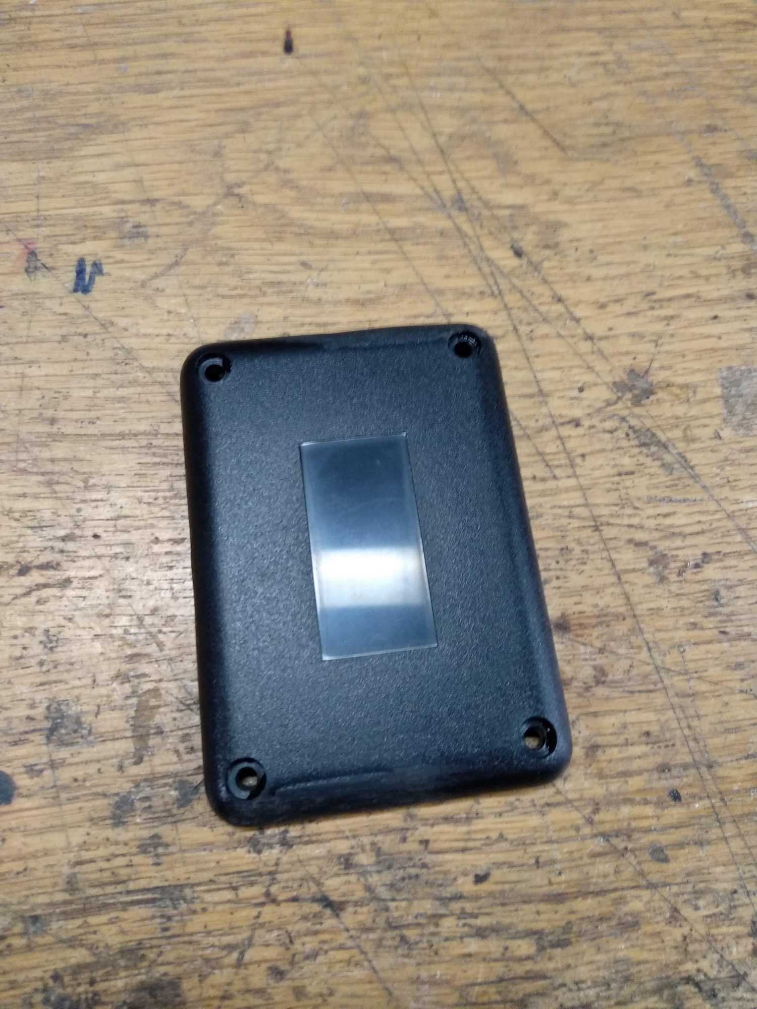
And the final thing looks like this:
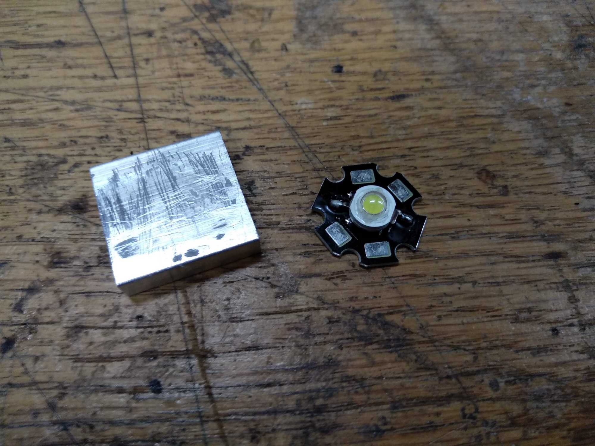
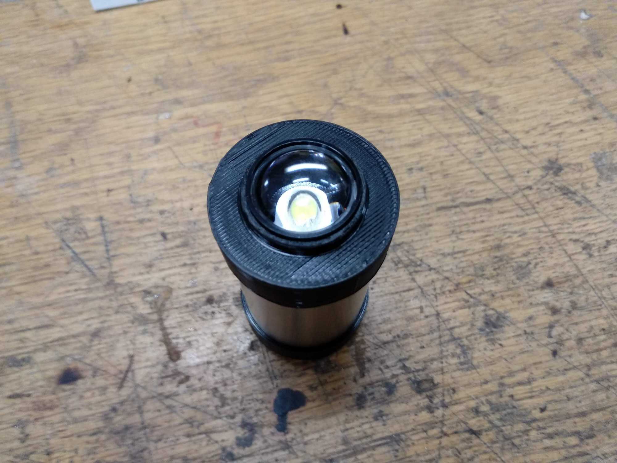
The light
Next I made the light. I used a high-power 5W (192lm) LED, which has a Vf of 4v and max current of 1200mA and running the LED on max power input for several minutes makes it heat up so much that you can’t take it to your hand.


I found a small heatsink which was ideal for such a thing and glued the LED to it using thermal glue. Also I added a heatsink to the boost converter, because I noticed it gets quite warm after a while.

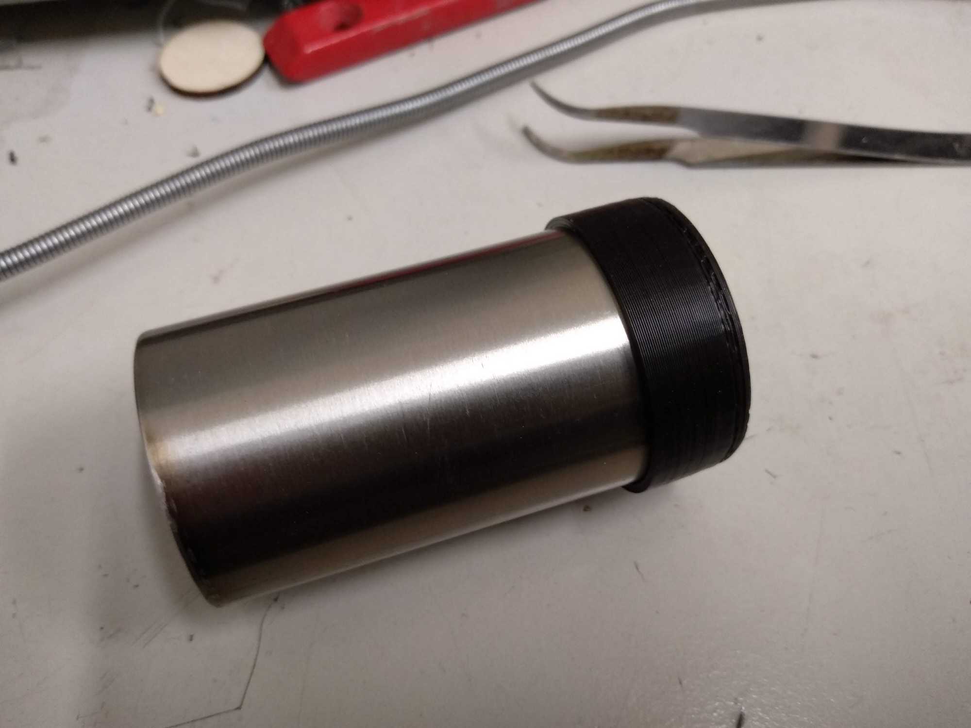
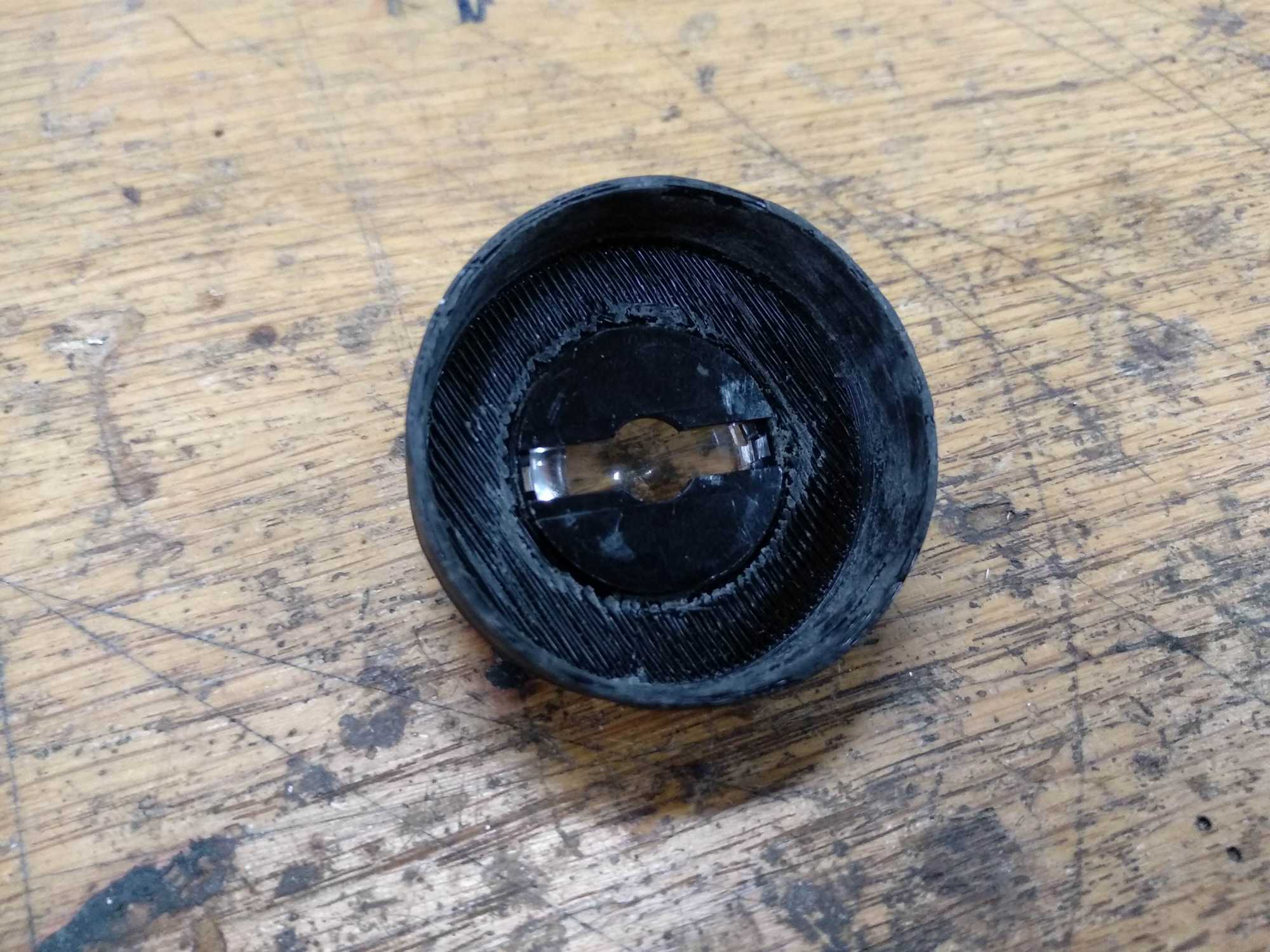
Everything was put inside a metal pipe, then I 3D printed the ends for it, one to hold a lens.


Receiver-dimmer
As for the receiver, assembly is essentially the same as the transmitter’s, but I was able to make it more compact since it has fewer parts – only Vin, Vout DC sockets, antenna socket, a switch and a red LED for status.


Controlling a high-power LED requires an external power source. To use that with an arduino, you need a transistor, I used a IRFZ44N MOSFET. How to connect everything you can find many tutorials elsewhere, but a diagram from this website makes it clear:
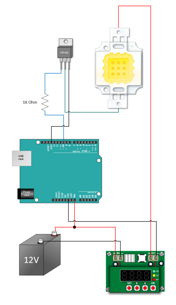
For the power-source I used the same input as for Arduino itself, so it runs through the receiver unit. And everything essentially is finished:


It is still missing a way to attach the receiver and the flashlight to something, but I left that out for the user to figure out.
Power source
Lastly I wanted to make a powersource. I didn’t go for a giant powerbrick, that would of been unpractical. I wanted to use a powerbank, but with replaceable cells, so I can use my own.
So I found a couple old laptop batteries, ripped them apart to get the LiPo cells inside.
They all were discharged to 1.80-2.50v which is very low for LiPo cells and knowing how fragile they are, this decreases their capacity. Since these haven’t seen a charge in quite a while, they needed to be refreshed following some simple principles and guidelines.
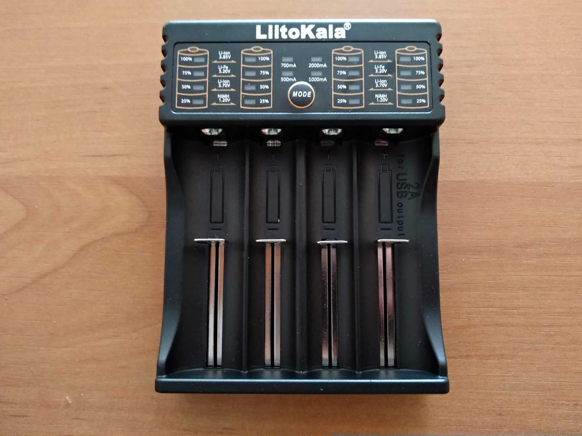
Best option would be to use a charger like that “iMAX B6” balance charger because you can force charge your cells if some are damaged deeper, it has a discharge function to test capacity and etc., but instead I bought a cheaper Liitokala “smart charger” from AliExpress which proved to be pretty good and along with that a simple discharger to test the capacity.

First I charged all the cells up to 4v and left them for a couple of weeks to see if any cells drops voltage – those can be thrown out right away since they don’t hold a charge and trying to revive them is useless because you’ll get a very low capacity cell.
After that I did a discharge-recharge cycle while testing the capacity when discharging. Wrote down the capacity and assembled a powerbank.


The powerbank looks big and heavy. Not for carrying daily :P
Code
The code that I wrote for this can be found here for the receiver and here for the sender. I’ll explain a bit what they do.
The receiver first setups the LED’s and checks if LoRa can be initiated and if not – it shows an error by blinking the status LED and stops further execution.
If everything is fine, then it registers a callback that fires whenever a command is received and puts the radio in listen mode.
The callback reads the packets to construct a message (I only send numbers whenever a pot is turned), but the decoded number fluctuates a bit and if I use that then the LED appears to flicker if you look carefully. So to even this out, I round the number to 10th’s and check if it exceeds 255 (which is the limit of int for the analogWrite()). Then finally I check if the received number is the same as previous one – I probably don’t need this, but IMO it’s good to not call analogWrite() if you don’t need to.
The sender works like this – it sets up all the stuff like LED’s, initiates LoRa with same params and sets the highest RX value. Same procedure with status LED as with the receiver.
Next it checks the battery status by probing it and doing some calculations. If the value is less than 3.6v then a yellow LED is lit up.
Then it reads the pot value and rounds it up as well – this is to remove random fluctuations, because the pot being in idle changes values slightly. Then it sets that value for the indicator (blue) LED and sends that value out.
And that’s it for this project.
Later I will post about experiences from the user after they’ll use it. That might be in a month or two.