
Attention! This prototype has evolved into a product and is now for sale on Tindie! https://www.tindie.com/products/makerspacelt/airsoft-bomb-prop-kms-ant/ and also has its own product page: http://armory.makerspace.lt/
You might guess that I’m an active airsoft player and like to bring in some innovative stuff to gain advantage for myself, like the foldable slingshot and just recently I wrote about remote detonation device that proved to be quite useful. This time I wanted to make some game prop because sometimes me and my team make a game to play for ourselves and we have no proper way of controlling our matches.
It’s not something new, but it sure adds new experience and makes for a better game. And the game prop is a bomb… with multiple modes. There exists many versions and ideas, some are very cool indeed, but I wanted to keep mine simple in regards to how it looks and universal in how it works, but not too much.
Everything will have to be connected to a custom PCB (to save space and to look more cool :D) and controlled by ATmega328p microcontroller (don’t need no arduino for this kek).
But if you want to make it even simpler, you can just go ahead and use an Arduino Nano or something on a perfboard. But if you have access to PCB manufacturing tools, then that’s the easier way to go and if anyone wants, I can send you my PCB and schematics.
I didn’t want this project to become a feature creep and tried to only filter out the ideas and features that I and my team would use in games that we do.
I read a very good article some time ago on this, which supplements what I had learned from a very good Raskin’s book, which I reviewed here. I always try to keep UIs simple and understandable, because I too am lazy.
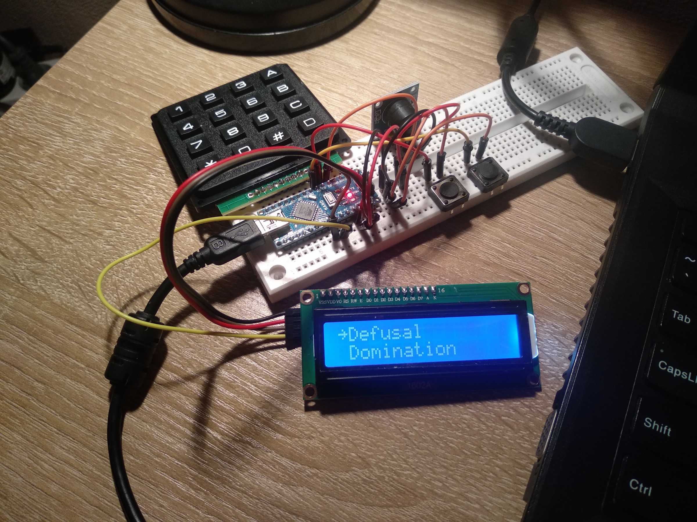
The modes that I wanted to have are defusal, domination and a game timer.
Here’s what each of the modes mean:
- Defusal – Some call it “Search and Destroy” and it’s the most basic mode, I guess. It’s what Counter-Strike games revolve around. Terrorists have a bomb and their goal is to plant it somewhere and make sure it explodes. Counter-terrorists have to stop them and defuse the bomb if they have to. I made this mode to be played with or without a code to activate and disarm with.
- Domination – Each team has to start their timer and stop enemy team’s timer. Whoever has accumulated most time points wins. Played with two big buttons.
- Game timer – It’s a convenience mode to start and stop the match if we were to play deathmatch.
- Sabotage – I didn’t add in this one specifically, because I feel it’s unnecessary to have a separate mode for it. It’s similar to Defusal, but the bomb sits at the bomb site and each team try to activate it. When activated, the other team try to defuse it and activate it themselves. Once activated, time begins to count until explosion. When defused, time is counted for the whole game.
This mode is a mashup between Defusal and Domination. So I just added a pre-game delay setting for Defusal instead.
Like I said, there exists many versions, and you can find code to use, however most that I found were very badly written, hard to understand and modify to my needs. So I decided to build it from ground-up because that’s really the only way to be sure that it works and of how efficient it is (not saying mine is extremely efficient, but I can modify it much more easily).
The code repo can be found on my github here.
I have tried my best to keep the code simple and easy to modify. Did I succeed – you tell me. But it’s probably most readable of what you can find available :D
The libs that I used for all peripherals were LiquidCrystal_I2C, LcdBarGraphI2C (this one I had to find online and edit to compile, so because it’s a bit obscure, I included it with the whole code), and the main thing – LiquidMenu for whole menu handling.
I have seen other projects trying to make out their own menu management, but IMO that just adds unnecessary complexity to the whole project and why would you want to do that anyway when there exists MANY different menu management projects?
I suppose they want to have a very tiny memory footprint without any clutter, but shit, I was able to fit my whole code on Atmega328p without a problem with half its memory and RAM to spare EVEN with Serial enabled.
However with a broad range to choose from I wasted a lot of time learning many different libs and eventually realizing that it won’t work for me until I eventually settled on using LiquidMenu after a few weeks of using it in various ways. It proved to be perfect for this project.
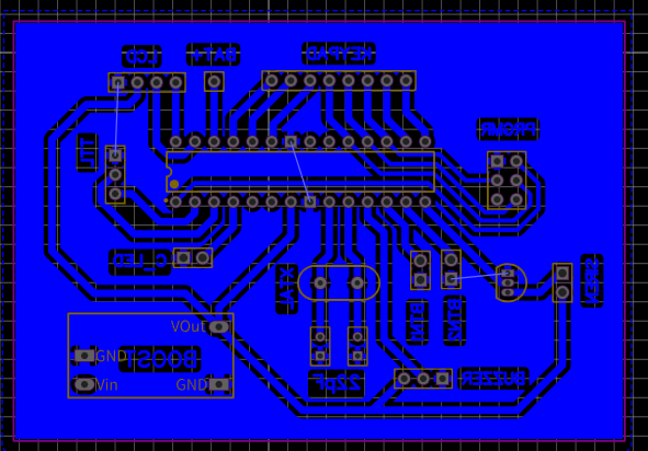
So with that out of the way, I started to draw a schematic with EasyEDA. And made a PCB too.
Notice that the siren is activated by a transistor. I used a S8050 but probably any NPN one will be ok. The siren requires very little current (up to 100mA) and the one I used works from 5V.

Now onto manufacturing!
This was my third time attempting to do this and it went quite well. Previous times I was making PCB’s for REMDE. Although the final PCB looked like shit because of the bad printer toner coverage.
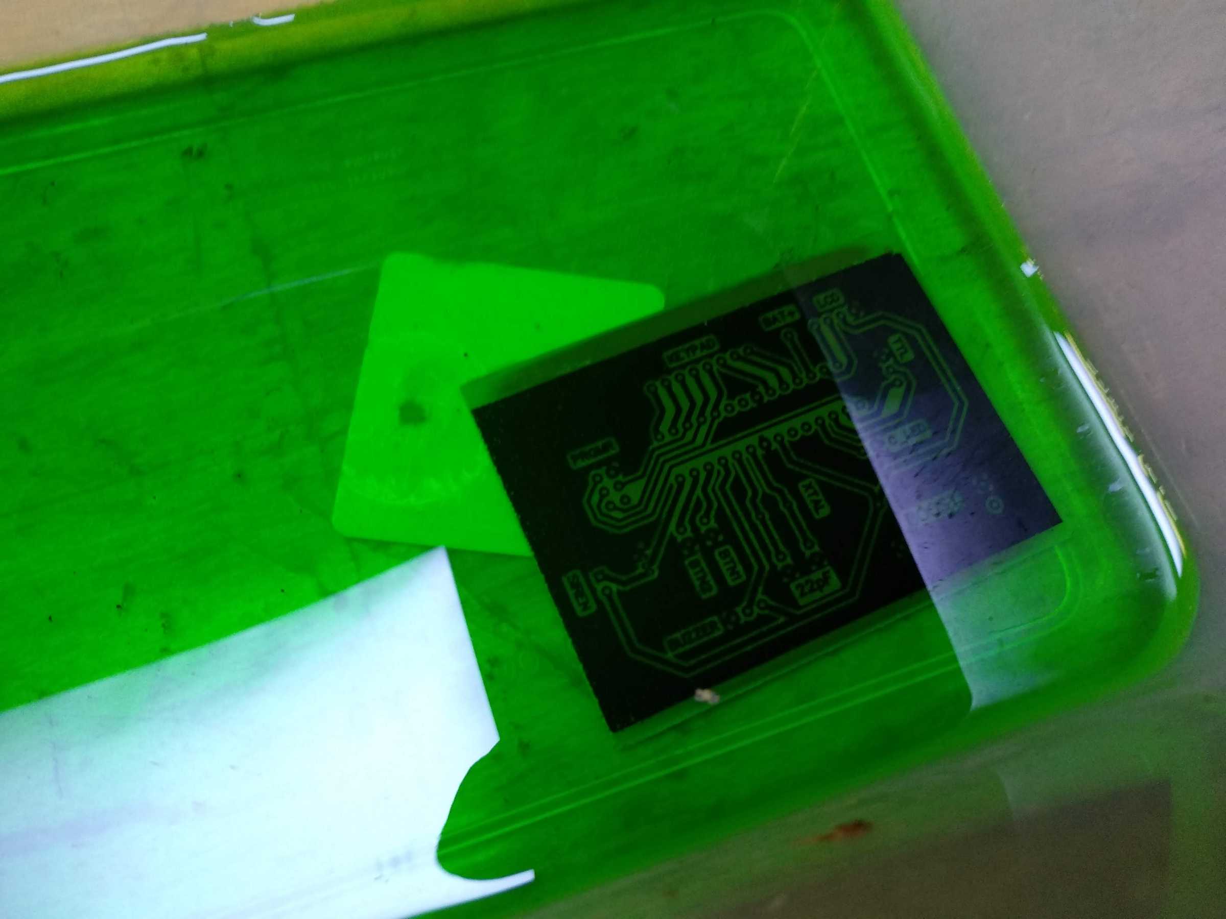
The process is simple – I printed my PCB on a special toner transfer paper, then used a gnarly looking device made from salvaged laminators to transfer the toner onto a piece of copper-plated template. Then I dumped that into a solution mixed from muriatic acid and hydrogen peroxide. After a while the copper was eaten away and I had a PCB. Then I covered the board with solder and drilled the holes.
It’s very important to double-check the quality at each step and be very careful about everything, because there’s many things that can go wrong and ruin the PCB.
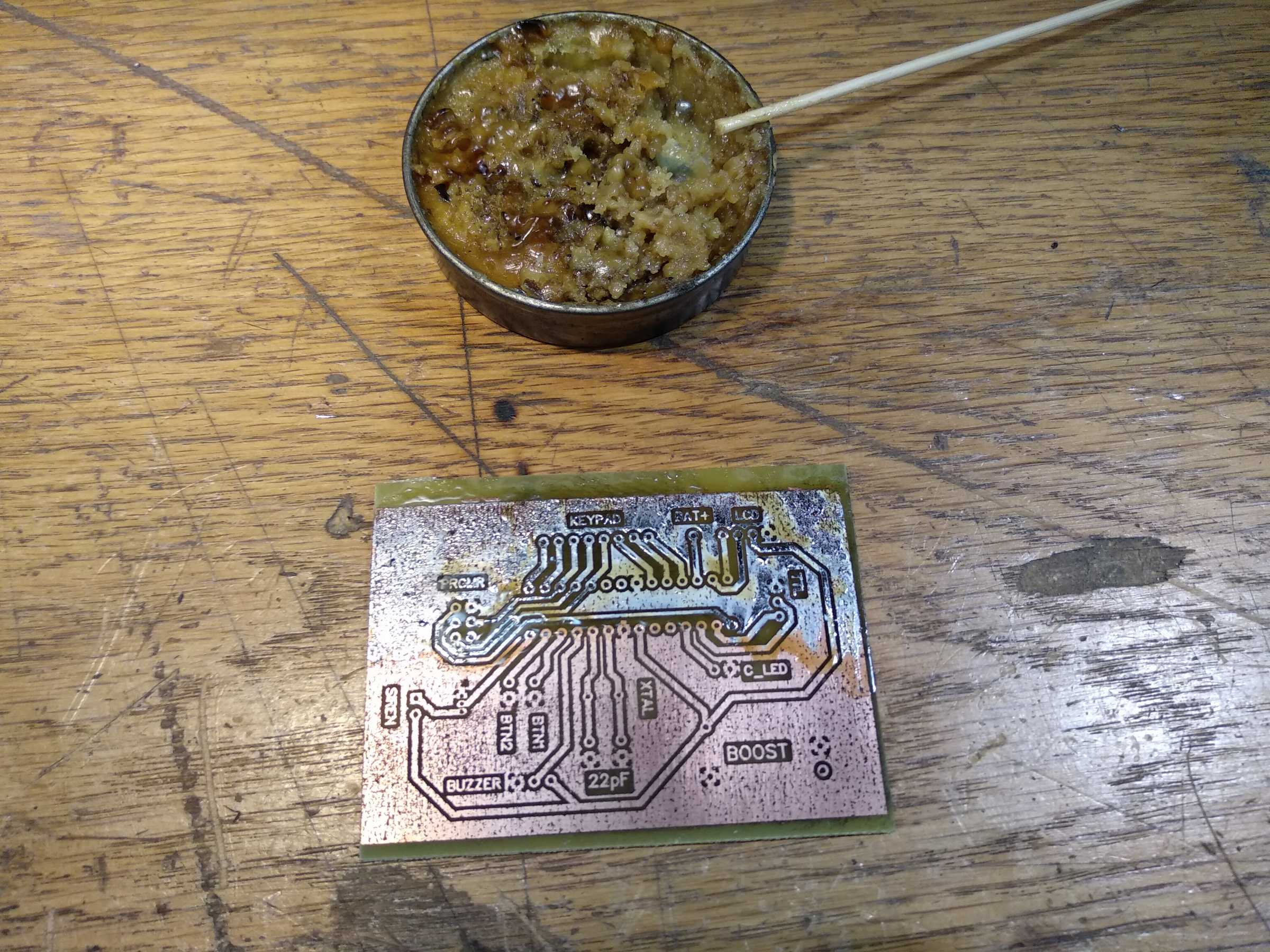
In my case you can see that copper is not solid and with holes. That’s because the PCB was printed very poorly, but it doesn’t exactly matter for the ground and I inspected the tracks and they all were ok. Though the PCB now looks ugly but whatever :D
After that I soldered all the components on there to get a motherboard :D

And when I powered it up, right away I noticed some weird things happening and I was certain I made everything correct.
Mainly (along with a few others) the problem was that there was voltage all the time on siren pins for whatever reason. I checked the transistor, replaced it, inspected all the tracks and pads many times, probed different areas and nothing seemed to fix it. I spent the whole day trying to solve them. And eventually, while looking at my schematic and the PCB layout for a long time I understood one thing – my GND net was divided into smaller areas by tracks and therefore there wasn’t a common ground to close the circuit. FML I thought, so a simple fix was to bridge those ground areas to the main ground and everything worked perfect after that.
I also added a 1k resistor on the transistor base which I initially forgot.

Lesson learned here – always make sure the ground is common everywhere.
Ok, so now the motherboard was working correctly, I went ahead to make a case for it. For that I used a large plastic project box that I had laying around and everything fit very compactly.
Another thing I didn’t consider was to check where and how I could place my PCB inside the case because the box has a very nice location on the side between the screw columns at the corners and the PCB could slide in there very neatly, but I didn’t know that and now my PCB is about 4mm too wide and doesn’t fit :D oh well…
So I made some holes…

Then I made a battery with a spot-welder, some connectors and added wires to the charging module.

And then just assembled everything.

So the final thing looks like this:

This thing is controlled with buttons A, B, C and D on the keypad. With A and B you navigate up and down, C is to select or clear user input and D is to go back. With D you can also cancel the current game by holding it for 3 seconds. Once the game mode is finished, you can press C to start over or D to return to the main menu.
By holding the green or red buttons when turning it on, it will display the battery level on the screen. Additionally, when battery voltage drops below 3.4v a yellow LED will light up indicating that it’s time to charge.
Now initially I didn’t consider how much the siren will be damped once the box is closed and it’s not loud at all, so it’s a problem because from very far it can’t be heard clearly.
I thought of drilling holes, but I don’t want to make the box with holes of I don’t have to, and also that wouldn’t make a big difference I think. So instead I thought of adding a socket on the side which connects to the siren pins. This way I can connect another external siren (or any other device that works from 5v and doesn’t require more than 500mA to work) if the bomb wasn’t being carried around.
I’ll make that modification later once I get another siren and test out if the transistor is capable of driving both of them at once.
For future modifications, since I have around half the memory left, I might add an options menu so that the user can customize times (like how much time it takes to plant and defuse the bomb, or team switch time) and a few other settings, but I feel that it’s gonna add confusion more than it’ll be useful.
Adding more game modes is also possible, although I can’t think of any at the moment. Maybe if you have suggestions you could leave it in the comments?
And here’s a brief video of how it works:
And that’s pretty much it for this. If anyone wants, I can also make some and send it to you within the country (Lithuania) limits. If interested send me an email :)