
If you were reading my blog you probably know that I play airsoft for several years.
Here the sites that we play in don’t change often and in most places airsoft grenades can be used.
In Lithuania, airsoft grenades are essentially firecrackers with up to 1g of powder placed in a small container and filled with BBs, dry peas or anything that is kinda round and represents shrapnel. Very simple, effective and you don’t have to pick it up after using.
So, in that time I noticed that a device that ignites a grenade when I want to at a set location would be very useful when taking back positions from enemy whenever they would barricade themselves in and I dubbed thee – REMDE. For open fields, I’ve come up with a solution that I wrote about here to fling grenades much farther than I could by hands.
The device functions very simply – the bare minimum is made up of two devices – the transmitter and the receiver.
Whenever I go into a nice position that I know enemy is going to sit there when they take it, I place the receiver down somewhere, attach an e-match (the very same used for firework shows) to it and attach the grenade to the e-match.
Now when I need to, with one button, I can check it’s status if I have multiple receivers and I forget if I had used it. With another button I can send a command to ignite the e-match.
This project stems from a similar one I’ve done for controlling the light intensity but this time I wanted to use different components and make it a bit smaller. For this I really don’t need the whole Arduino. Therefore I used Atmega328P for the transmitter and Atmega8 for the receiver.
I also wanted to use NRF24L01+PA+LNA with external antenna as the radio module this time… just because I haven’t used it and the theoretical distance it can reach is up to 1 km. Though I am skeptical about it working reliably, because it uses the 2.4GHz band and it is pretty noisy there. I’ll have to do some tests with different settings when I assemble both units.
At the very beginning, I sketched out on paper how could my devices look, wrote a list of functionality requirements and how would those features work, ordered parts from AliExpress and started coding.
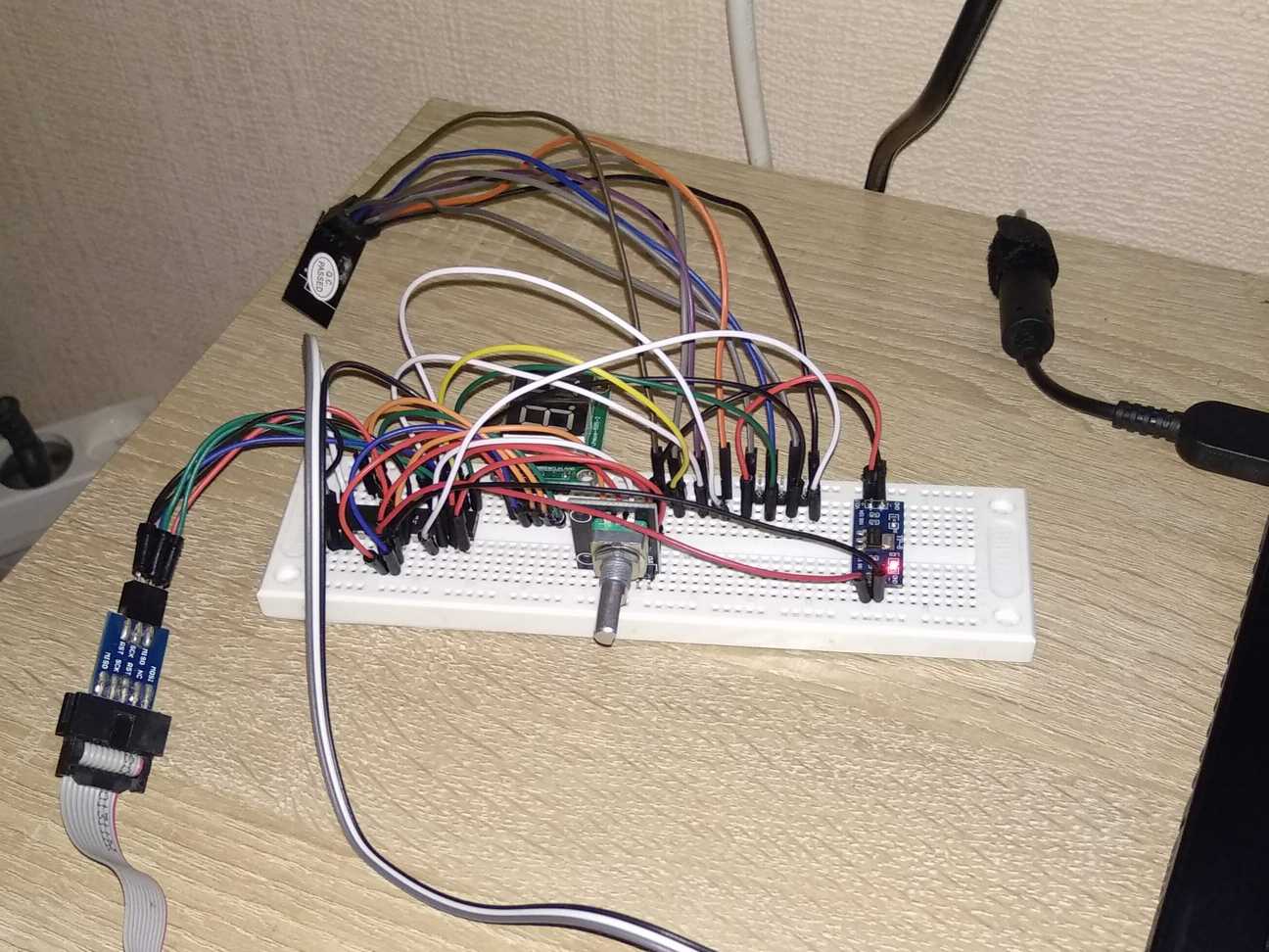
How the transmitter works, in detail:
When turned on it reads EEPROM and shows a number on the display. This number tells which receiver I am communicating with. Using the rotary encoder I select a device I want to communicate with and push the encoder button to confirm my selection to lock the device to that number and that number is written to EEPROM. Now I can press the green button to check its status or the red button to ignite the e-match. Device responses are shown on the display appropriately. If I hold down the status button while turning the device on, it shows me battery voltage on the display.

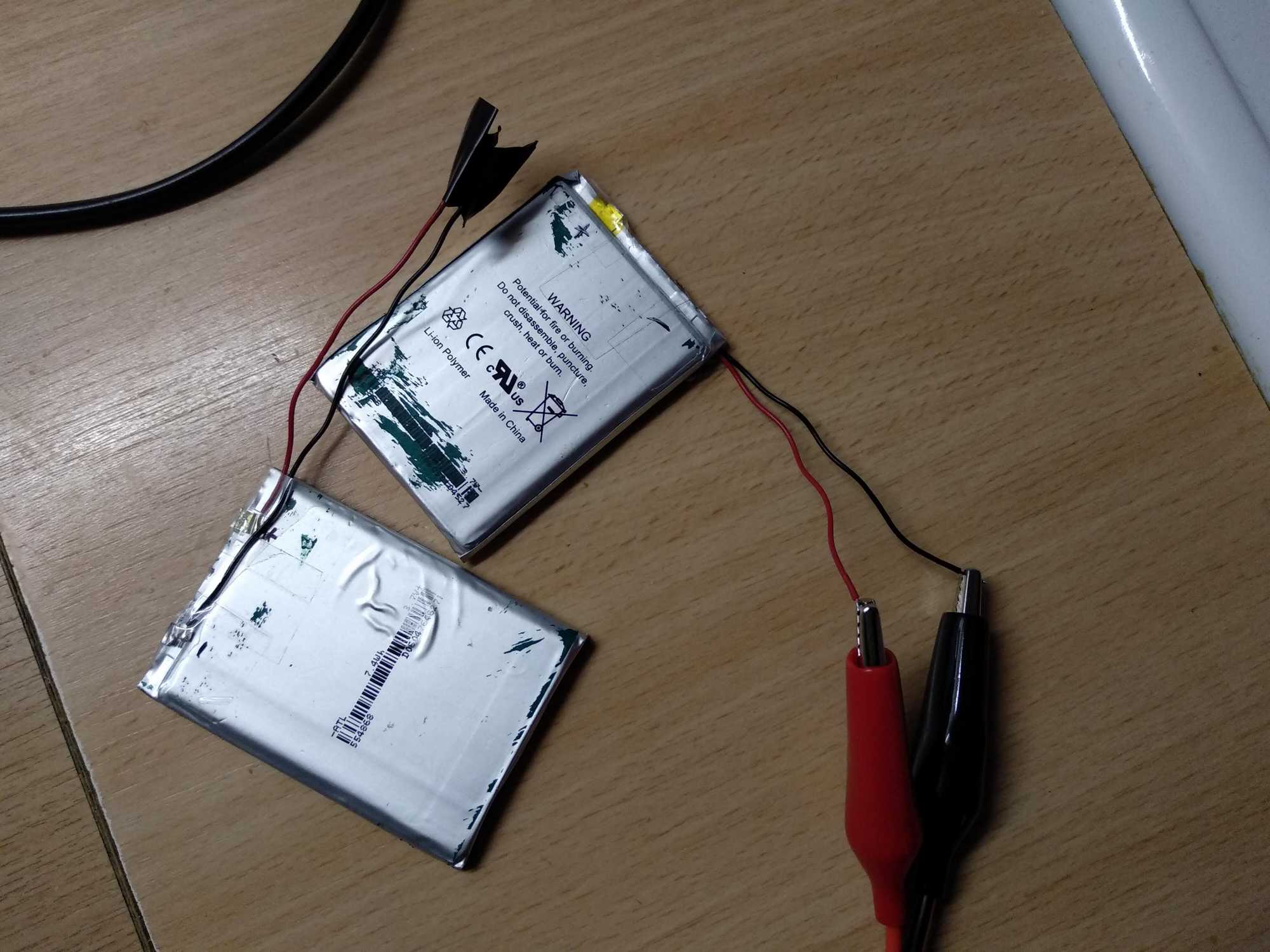
Meanwhile I also found and refurbished two unprotected prismatic LiPo cells that are still in a very good condition of ~2000mAh.

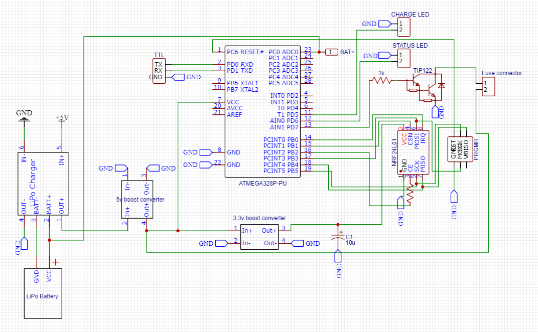
When it was all working fine on a breadboard, I used EasyEDA to design a schematic with a PCB layout for both the transmitter and the receiver.
Transmitter:


Receiver:

The transmitter
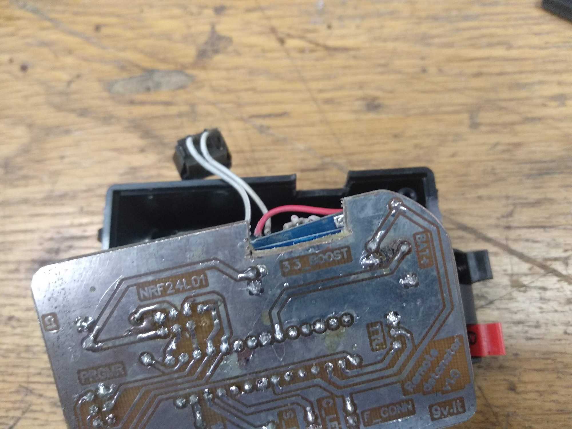
I etched the PCBs myself. It was my first time doing it and it turned out very nice :)
Be warned though, when covering the copper with solder, be very careful and double check all tracks and connections with a magnifying glass if anything is touching where it shouldn’t. I had a couple of very tiny connections between tracks left from moving the soldering iron. My circuit wasn’t working because of that and I spent a few hours trying to figure out why.


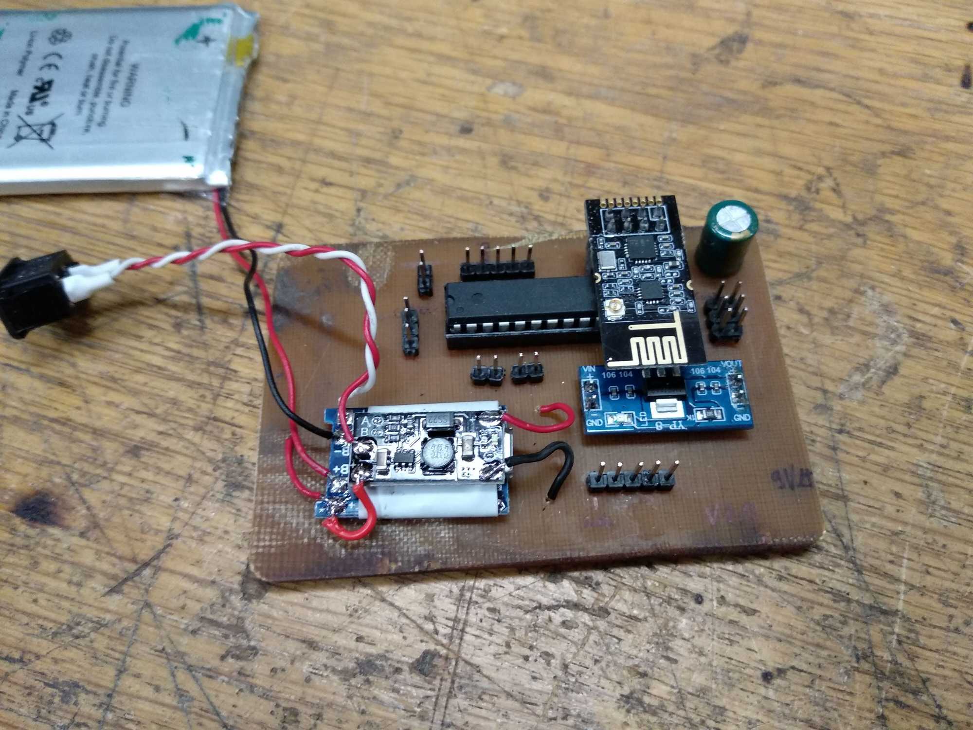
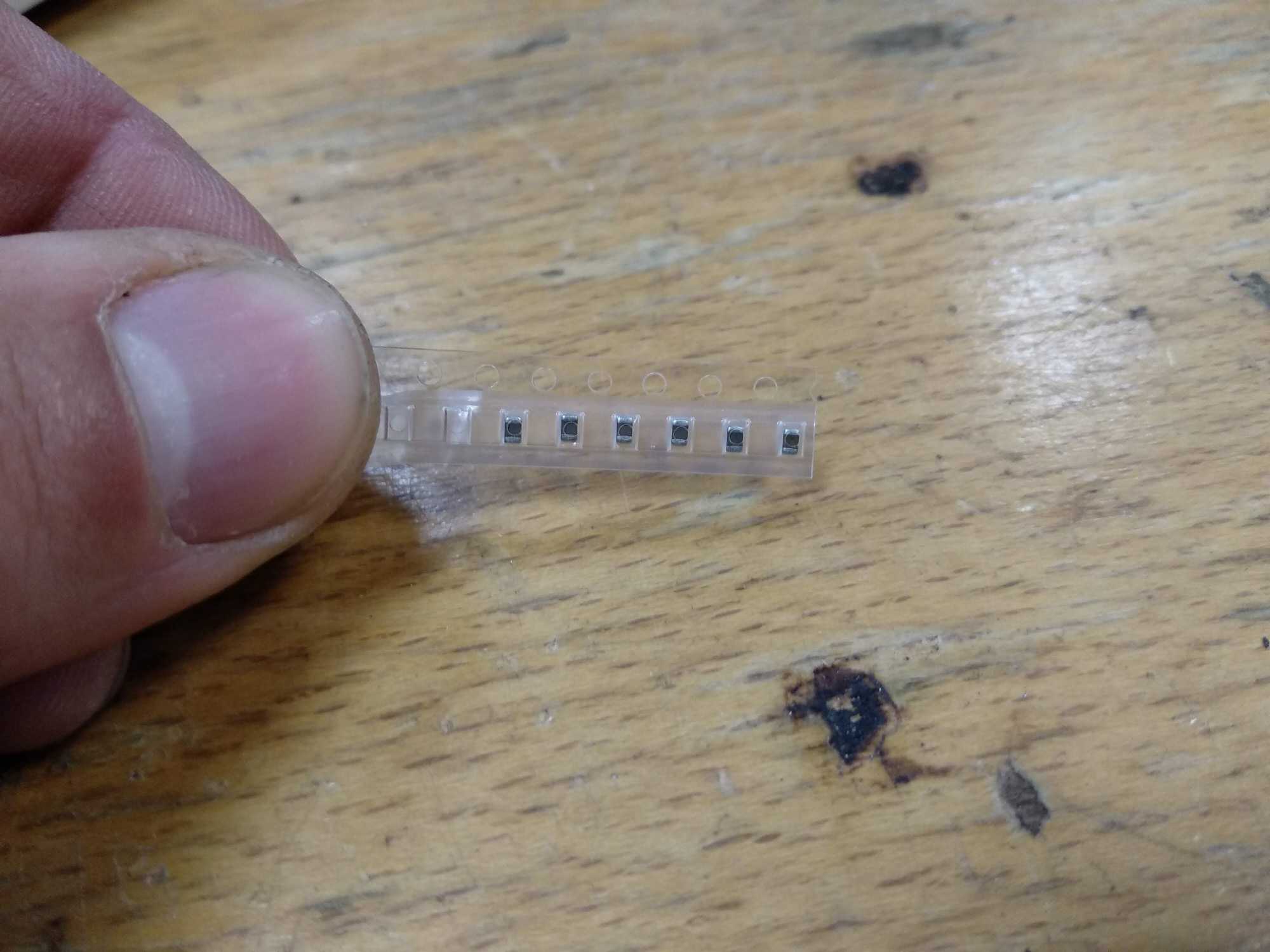
Notice the capacitor I added near nRF24. It’s recommended to add a capacitor directly on Vin and GND of the module of 0.1uF-10uF to equalize current surges it needs when transmitting. Without the capacitor, these modules just don’t send anything. They can receive with no problems though. Probably all of the Chinese modules need to be modified like this.
However, when designing the circuit, I thought I’d add a bigger cap (470uF 6.3v) and that’ll be even better, but turns out that wasn’t the case and the cap doesn’t do anything it was intended to do. Probably because it’s too far away or it’s not capable of discharging quick enough.
I then added 0.1uF SMD caps on Vin and GND lines of the module and that seemed to have fixed all of my communication issues.
Also a very important note – to make the radio module use its external antenna, a 0ohm resistor connecting on-board antenna to a pad must be desoldered and moved to other pads. This acts as a switch selecting which antenna you want to use. If you lose that component, you can use very thin copper wire to connect pads.

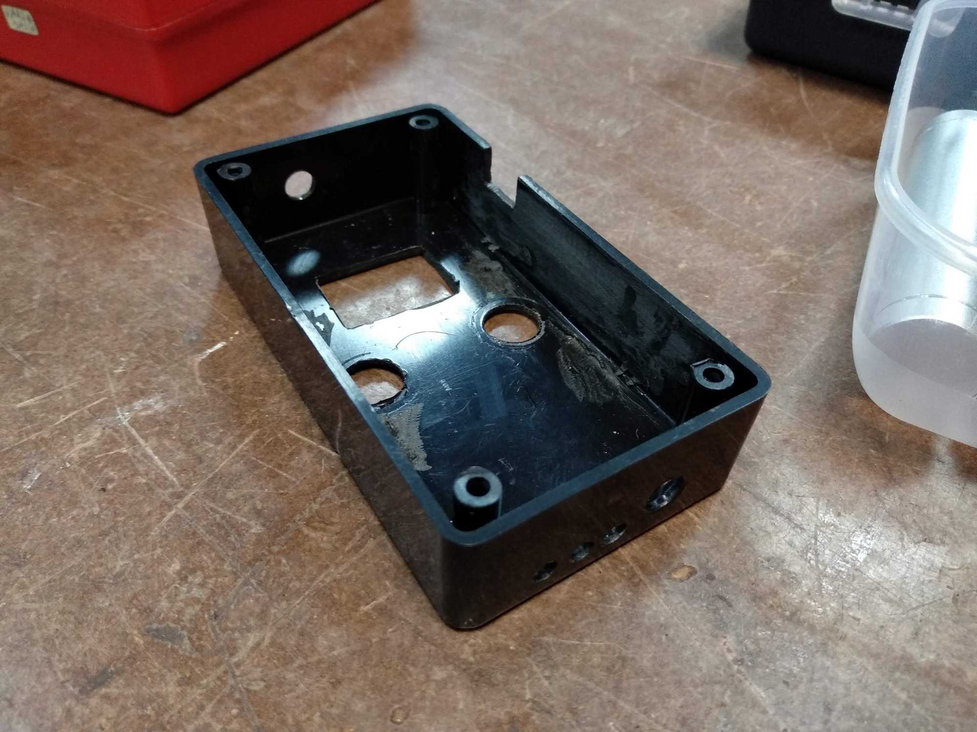
When all that was done, I bought a plastic case to put the transmitter in. Sadly there wasn’t one that would fit my project perfectly, so I went with the second best choice. That meant that I needed to design a back cover bracket to make the case a bit higher and 3D print it, because the battery doesn’t fit and the case can’t be closed.
I only had white PLA plastic at the moment, so I painted it black later.


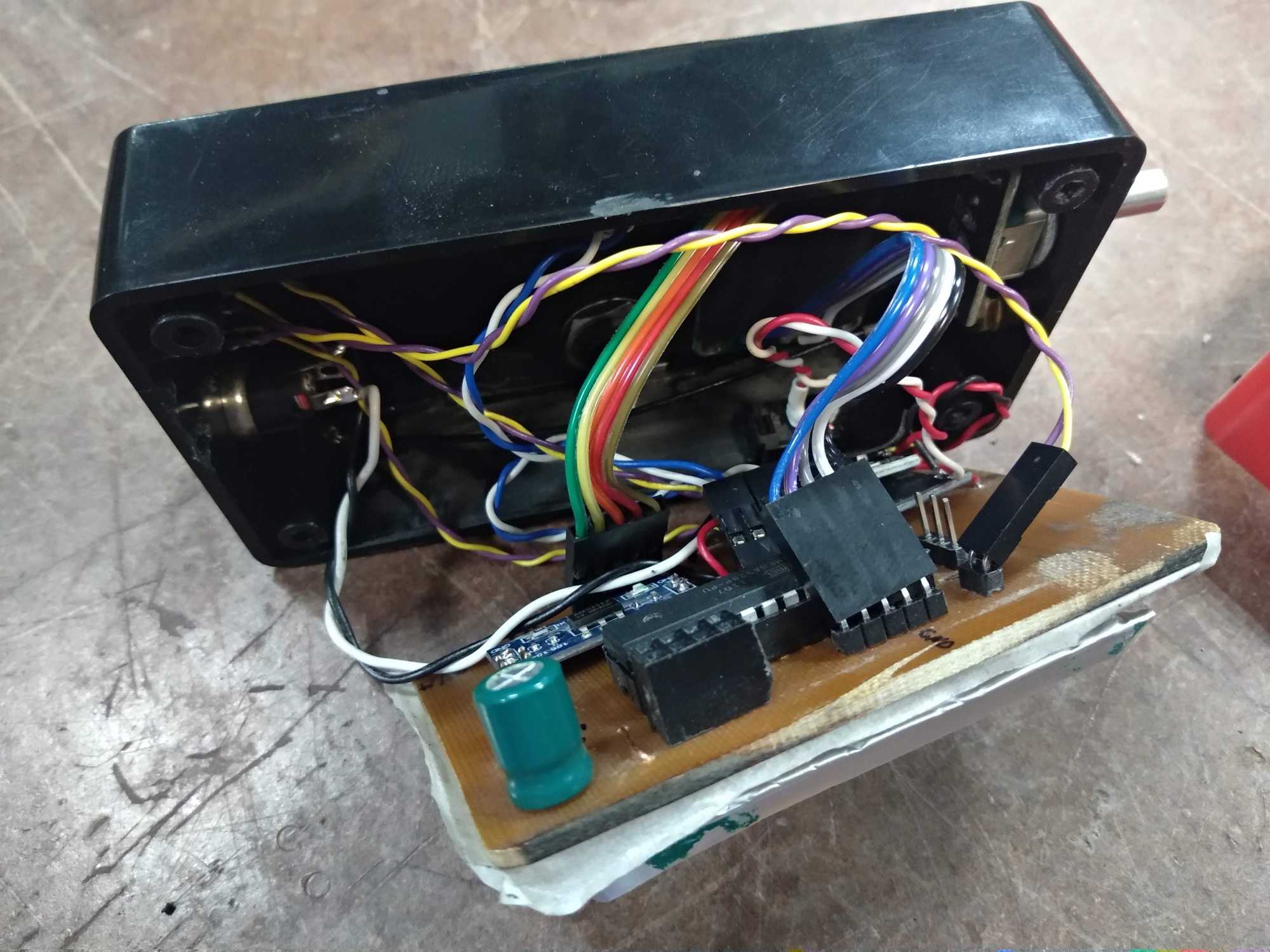
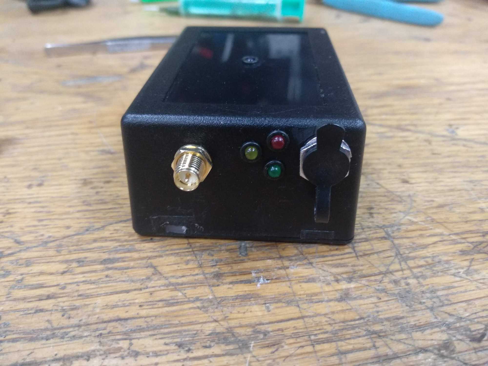
And finally I assembled the transmitter into that box.


The receiver
Up next I assembled the receiver. It’s simpler that it doesn’t use a display and a rotary encoder, but to ignite an e-match it needs at least about 100mA of current. To be sure of a stable flow I used a TIP122 transistor to use external power from the boost converter and not from Atmega.
However, later I realized that such a heavy-duty transistor is a bit of an overkill to use. So I later replaced it with S8050.
Essentially, it’s now possible to expand my arsenal with various receivers that do different things and all can be controlled with the same transmitter.
So when I had all the parts to assemble it, I first bought the case and I was very lucky to find one that houses my PCB and battery just right. However, I had to trim corners a bit to have the PCB fit.
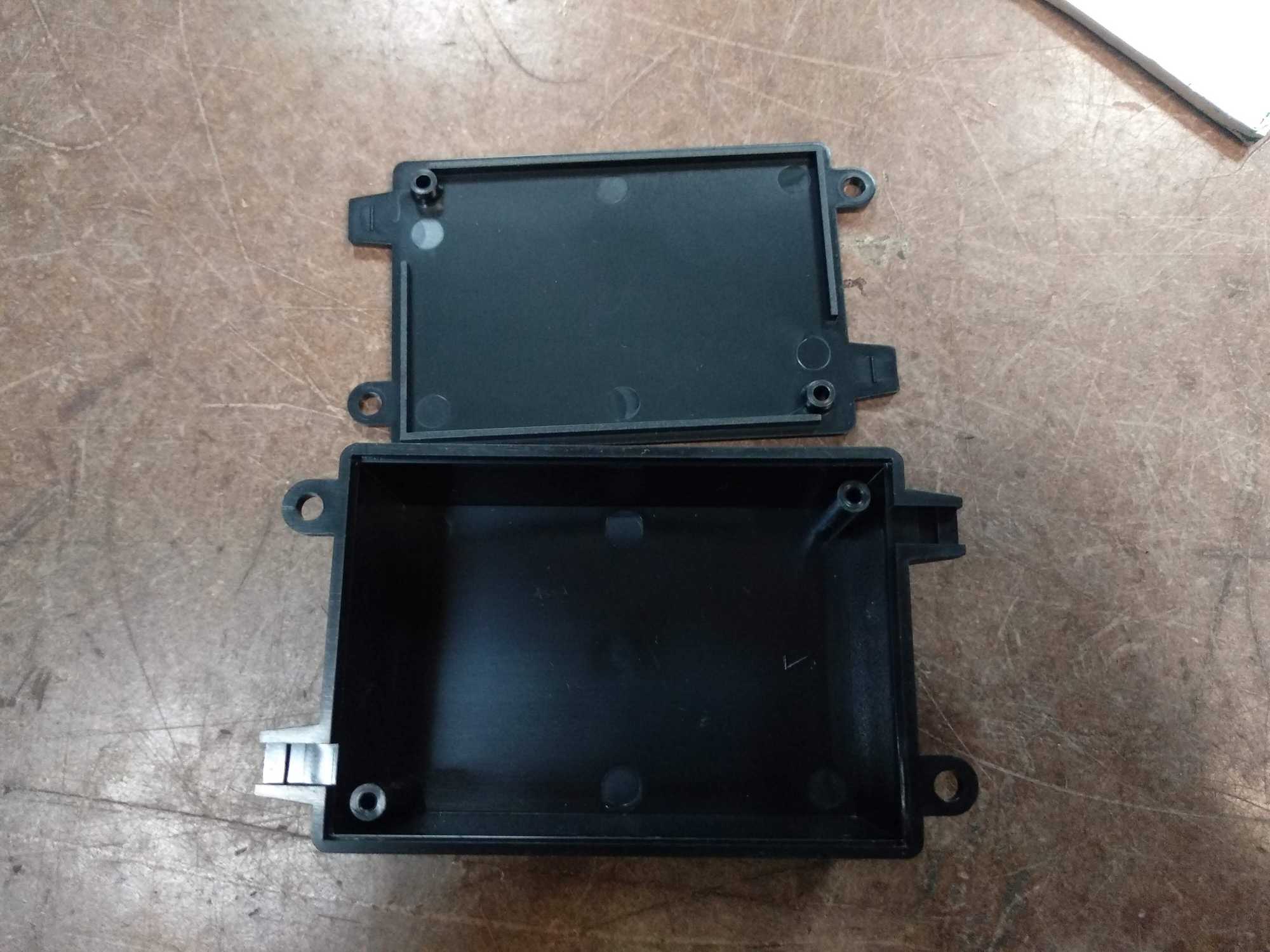


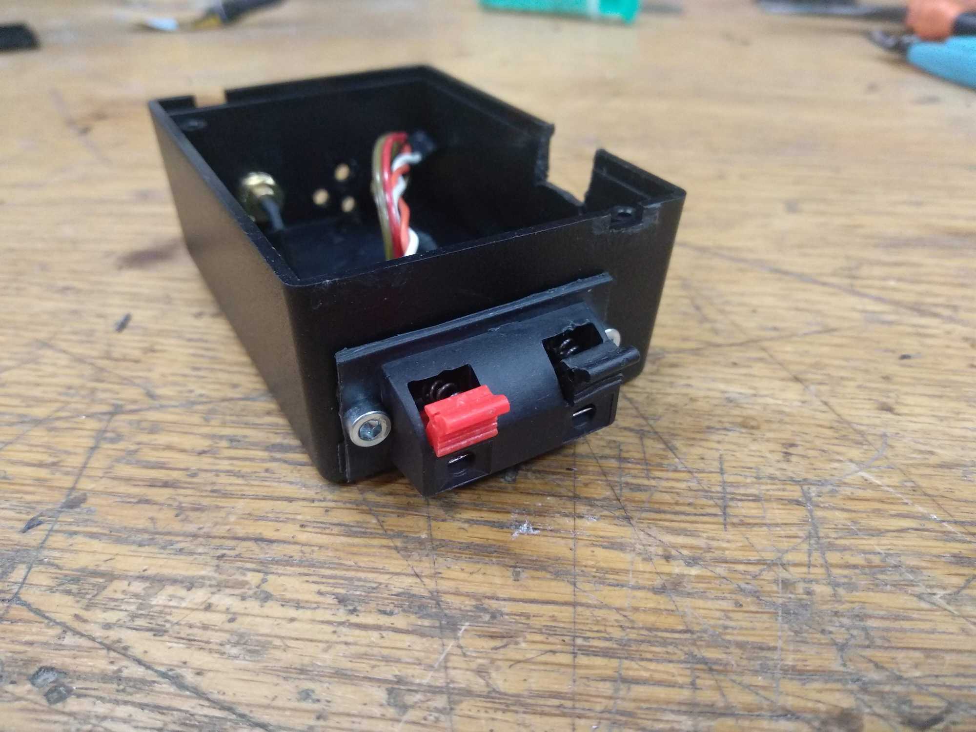

And of course had to cut out a bit of the PCB, because the button wouldn’t fit otherwise. Looks ugly AF but whatever :D
And so assembled it looks like this:


After the first test-run in a game, I realized that it’s not easy to deploy this fast, specially when others are shooting at you :D
Because of that sometimes the igniter wouldn’t get put in properly and the grenade would not go off at the needed moment. I didn’t think of this at the planning stage and didn’t do any way to check if I put in the fuse right. Later I added this feature by simply connecting the ground connection of a fuse to ADC and ATmega would read +5v on ADC if the fuse was put in correctly without firing it off.

How’s the range, bruh?
Well, theoretically PA+LNA modules can reach up to a kilometer in distance and I fairly believe it’s possible with my simple tests by changing different settings around.
My test was in an open, grassy field. I placed the receiver in the grass and then went away for about 500m. I could still communicate though and about every fourth request would go through.
I also tried the same test in a building complex but by placing the receiver on the ground the range was very poor – maybe about 30m. When I lifted it a bit by placing it on my car roof, the range increased dramatically. I didn’t measure the distance then, but there was probably a good 200m and then I concluded that for my airsoft purposes that’ll do, pig.
Later I tried in an open field away from the city where I placed the receiver on a column (so it was elevated) and drove away from it. If I kept a clear line of sight on about the same elevation level, using a default wifi antenna for both devices
I reached exactly 1km distance (+/- 10m). This is pretty damn nice.
However though, the range is VERY dependent upon the area you use them in. It depends much on radio pollution, obstacles it has to go through and other factors, therefore there isn’t a setting that fits all scenarios. I suppose if the device was used only in one spot, you could tweak its settings for that particular spot and it would work very well.
Grenades
The ones I make and use are designed for my “grenade launcher”, so they are compact. To use with this devices, I just add the e-match onto the fuse and that works.

Firmware for both devices
Since both devices use Atmega, Arduino framework can be easily used to write firmware for these devices and it’s pretty easy if you know how such things work already. To simplify the development VSCode with Platformio can be used.
The code can be found on my github: https://github.com/kulverstukas1/remote-detonation-airsoft