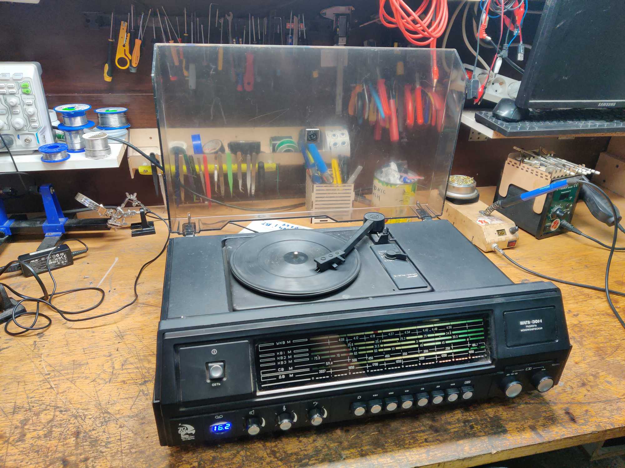
For reasons I’m yet to understand I like retrofitting antique radios with bluetooth capabilities. Mostly because I think that’s pretty cool.
A friend of mine asked me if I could put bluetooth into this radiola that he found. A radiola as a word doesn’t have a clear definition but soviets called that their line of radio-record player hybrids – a device that could play radio or vinyl records.
It was still in a good looking condition, though didn’t seem to produce any sound, also this particular model from 1983 didn’t have any way to listen to FM radio.
More information on this thing can be found on this website: http://rr20.ddns.net/Item.aspx?ItemId=b9a8734a-6275-4075-bfbe-4aa824ec6e5a&Lang=En
For retention’s sake here’s a copy from there:
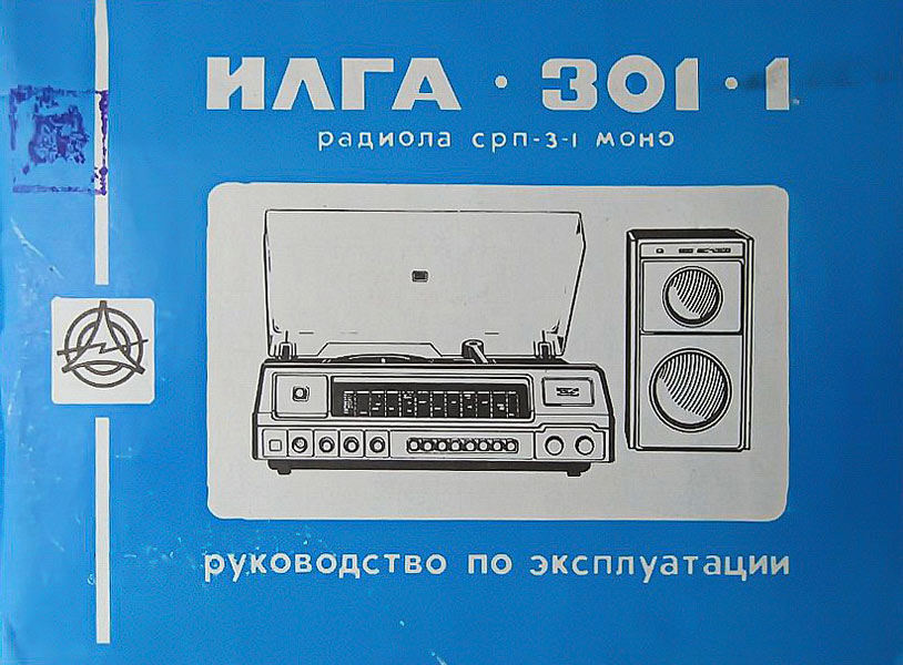
The stationary transistor radio “Ilga-301” has been produced by the Irkutsk Radio Plant since 1979. Radiola “Ilga-301” operates in the ranges DV, SV, KV (3 sub-bands), VHF, and plays records of all formats. The model is developed on the basis of the Vega-315 radio. It uses a three-speed EPU III-EPU-38. The Ilga-301 operates at the 6AS-9 AS, where the 6GD-6 and 3GD-31 heads are installed. The model has AFC in the VHF range, bass and treble tone control, light indication of the type of work. Sensitivity in AM 200 µV, FM 15 µV. Output power 3 W. The frequency range in AM is 100…3550 Hz, FM 100…10000 Hz. Power consumption 14/40 W. The dimensions of the model are 534x377x164 mm. Weight 16 kg. Price 115 rubles. Since 1981, the plant has been producing the Ilga-301-1 model, which, in addition to a different design of the AU, a different EPU, small changes in the circuit and more modern radio elements, is similar to the base one.

Said friend wanted for it to be turned on with the power button like it originally was, have a battery for some portability because its pretty heavy, have the screen lit up when turned on as it originally was, have volume control and output audio when the turntable is spinning, imitating a vinyl record playing.


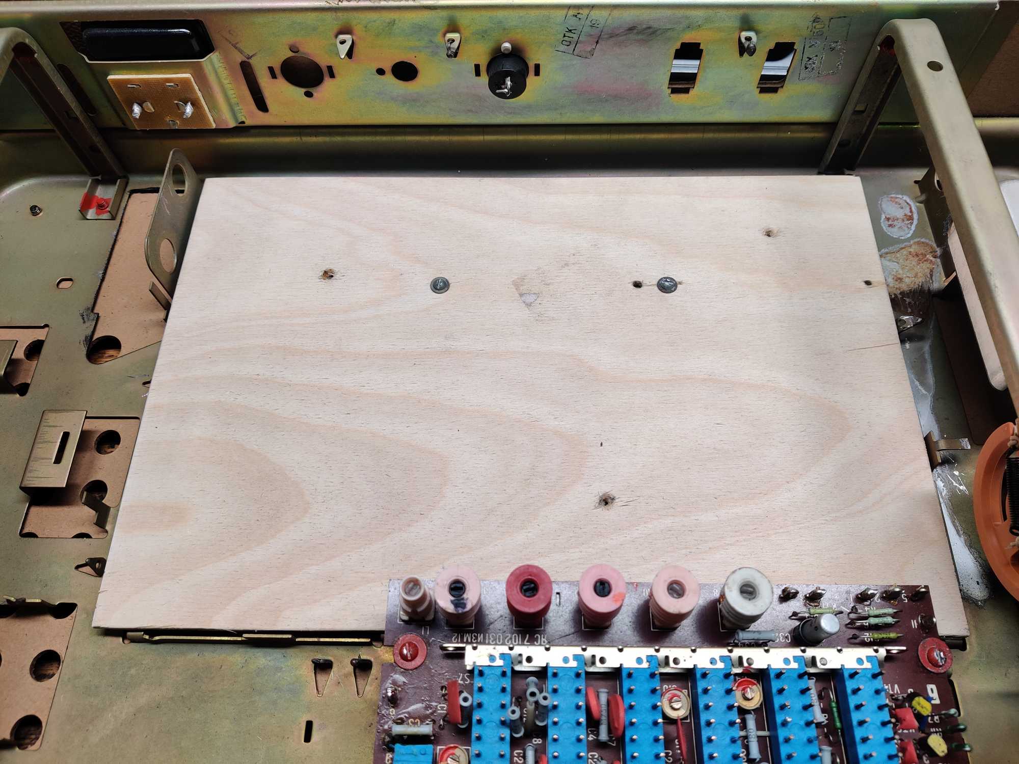
I started tearing it up and removing what I didn’t need which was most of the insides leaving space for new components. I only left the pieces that are responsible for parts of the interface and covered the middle hole with plywood.
Look at all the space for a battery!

After that I took a look at the turntable mechanism. It’s pretty gargantuan for this small task. The motor itself requires 180 AC to start turning! well obviously that part has to go out and I’ll need to replace it with a smaller DC motor which I tried to fit into the same spot to have a similar reduction ratio. Of course for this case it doesn’t matter how fast or slow the turntable spins, it only has to look like it’s at the correct speed.
This is how it looks on the inside:
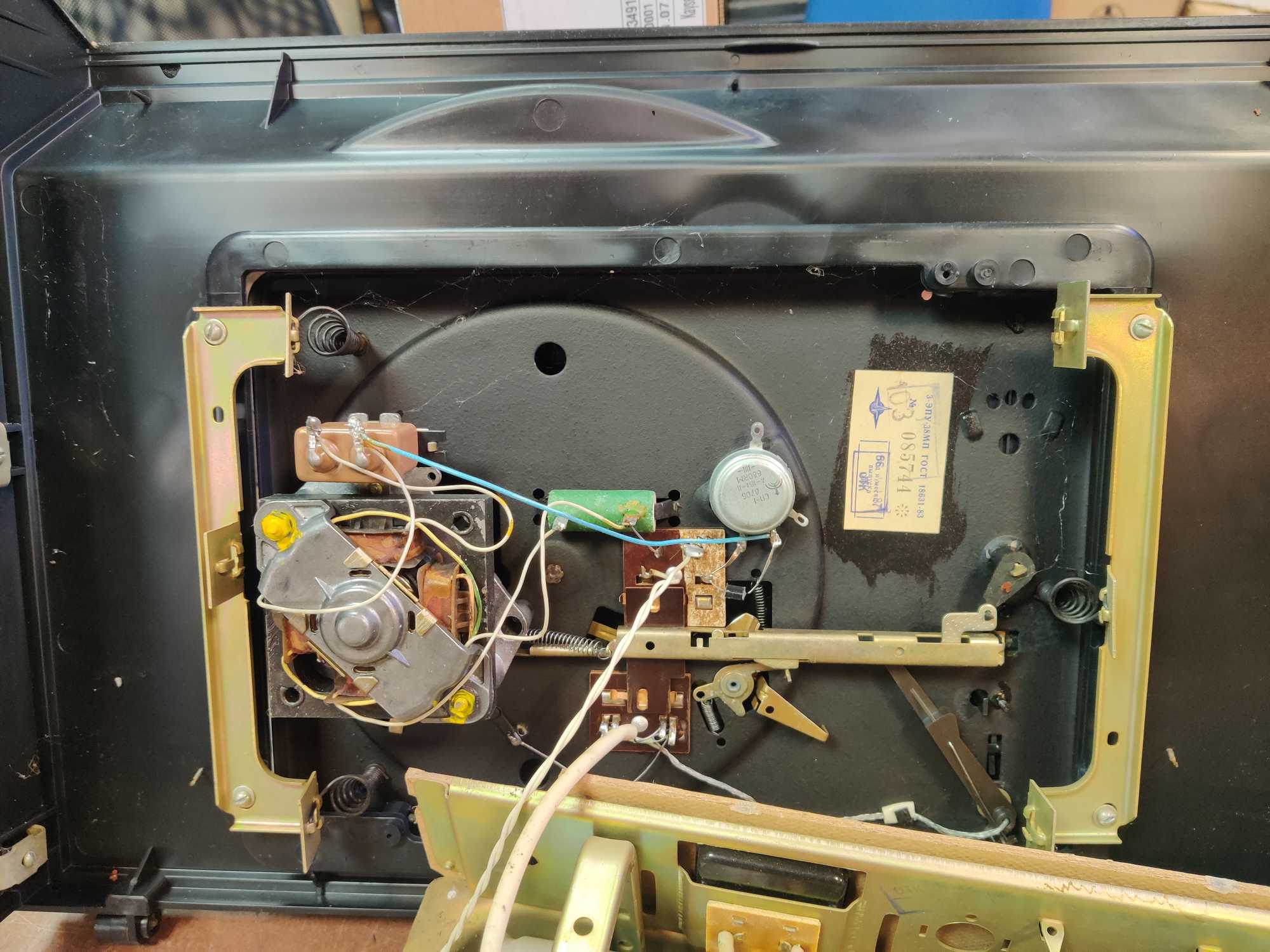
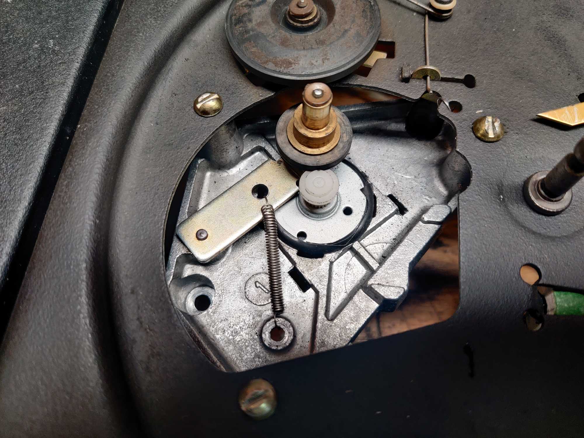
This is how it looks like under the turntable. You can see the motor axle is touching the middle rubber wheel which then spins the turntable:

I took that motor out and found a DC motor that could fit in the same place without custom brackets or something of that sort. It seemed that I had enough karma points for this one because the motor I found along with a gear for it was a perfect fit once I drilled a hole and used a bit of electrical tape around the motor to get a tight fit.
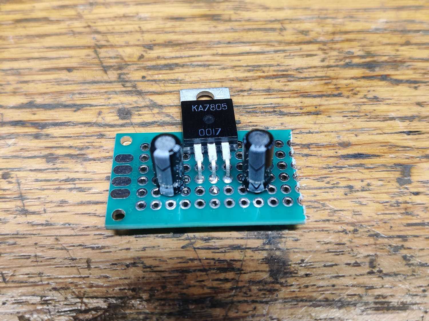
I also needed to limit the voltage to 5v slow it down a bit because visually it looks too fast and for that I made a DC voltage converter. But this part later burned out and was replaced with a more efficient buck converter.
Also I had to add a spring to hold down the arm that sits between that rubber rotor and the motor, seems to work better like that and the motor was fixed in place with hot glue.


Having done that what seemed to be the most questionable part of the whole project I started to put new parts around the thing – at the back I added audio outputs for both sides, a DC barrel jack for charging and a voltage meter. For the last one I took a file and made it fit, now the meter sits flush to the outside and is fixed with hot glue.


Having done that I started to do the wiring. First I placed out the components in an organized manner, added some wire holding bracket thingies here and there.


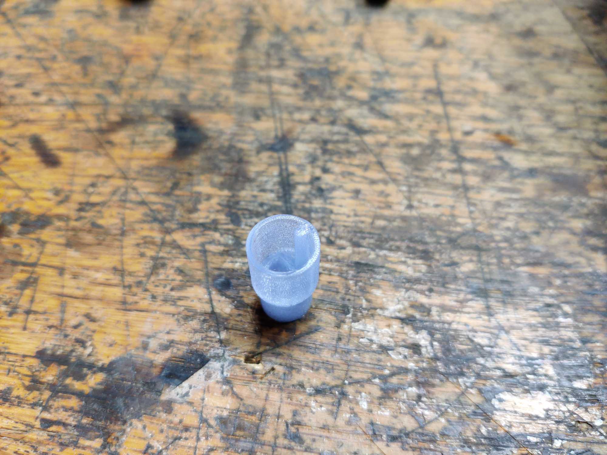
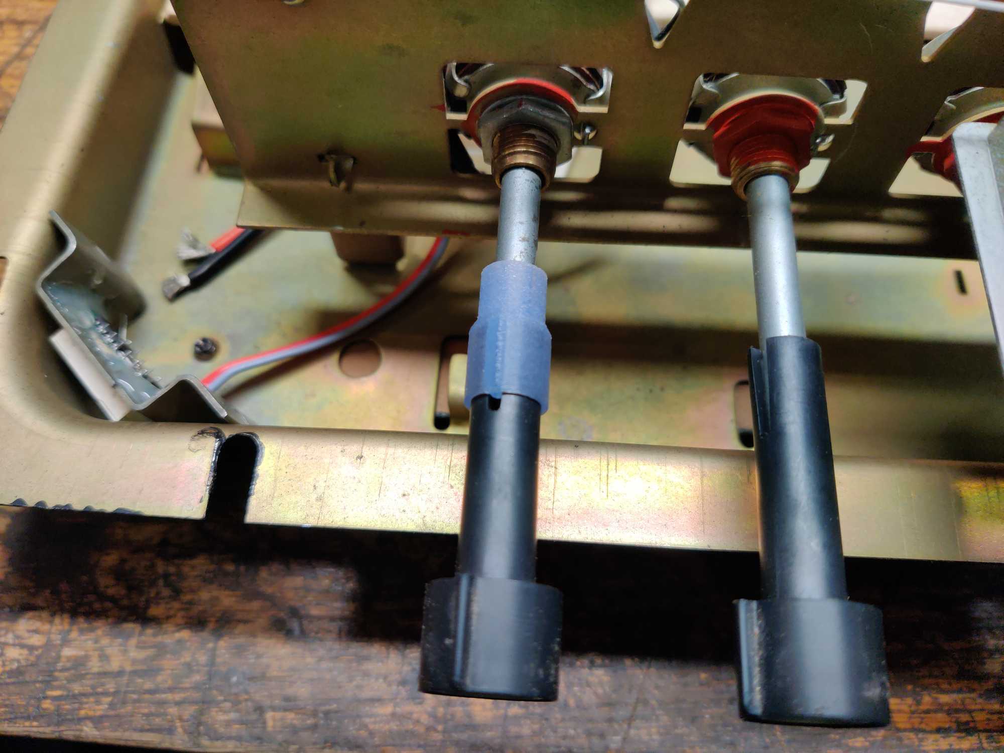
Since I wanted to have volume control like it was originally, I needed to replace the potentiometer which could control both left and right channels which I did but I only had one with a shorter rod. That wasn’t a very big issue because I could 3D print an extender which I did. But before closing it up I noticed the screen illumination bulbs that originally was in there are for 6 volts and I was driving them with 12v… that’s why they gave out so fast. I bought new bulbs (type E10) rated for 12v and put those in to solve this issue.
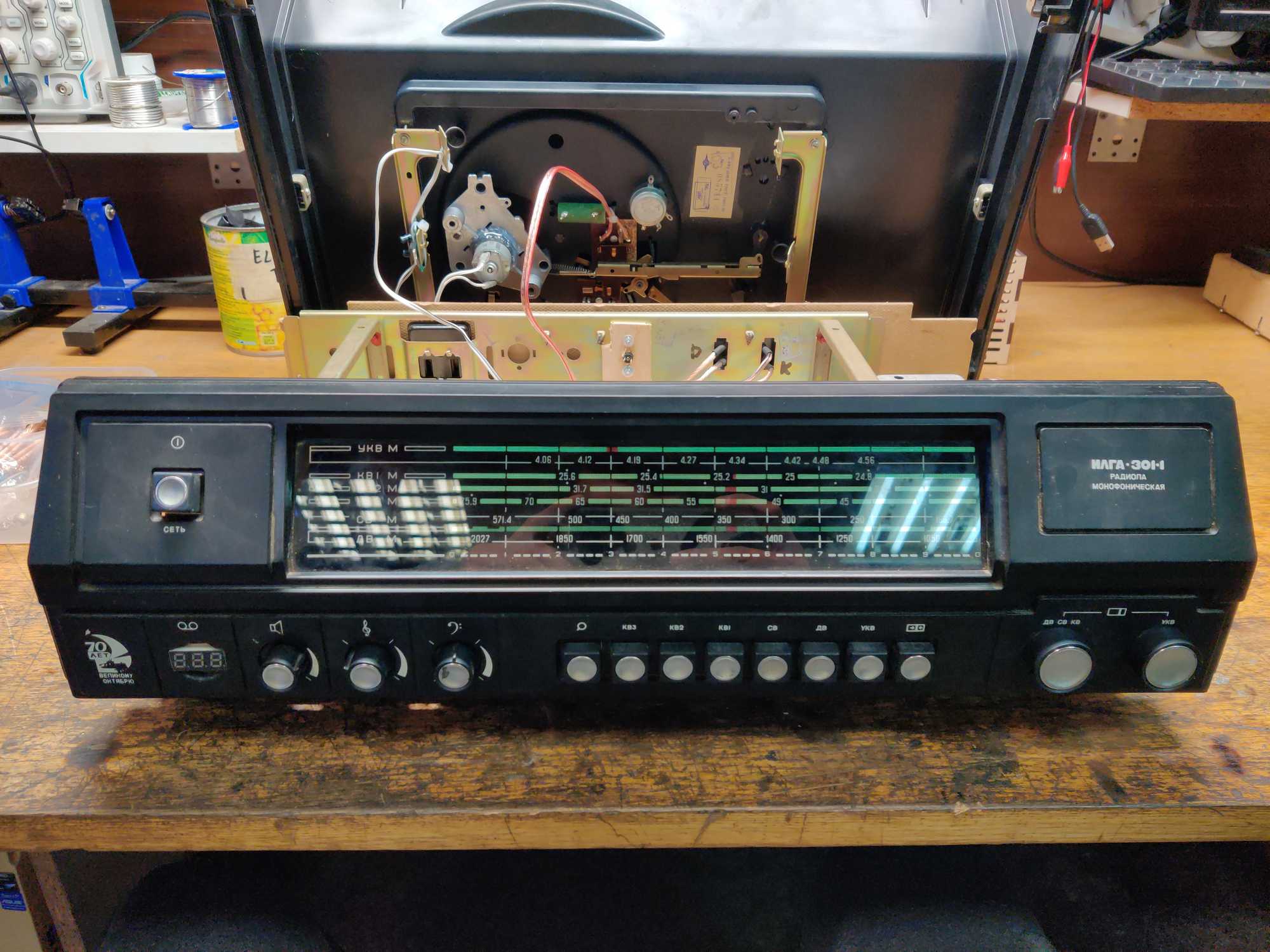
Finally I mounted the front panel on.


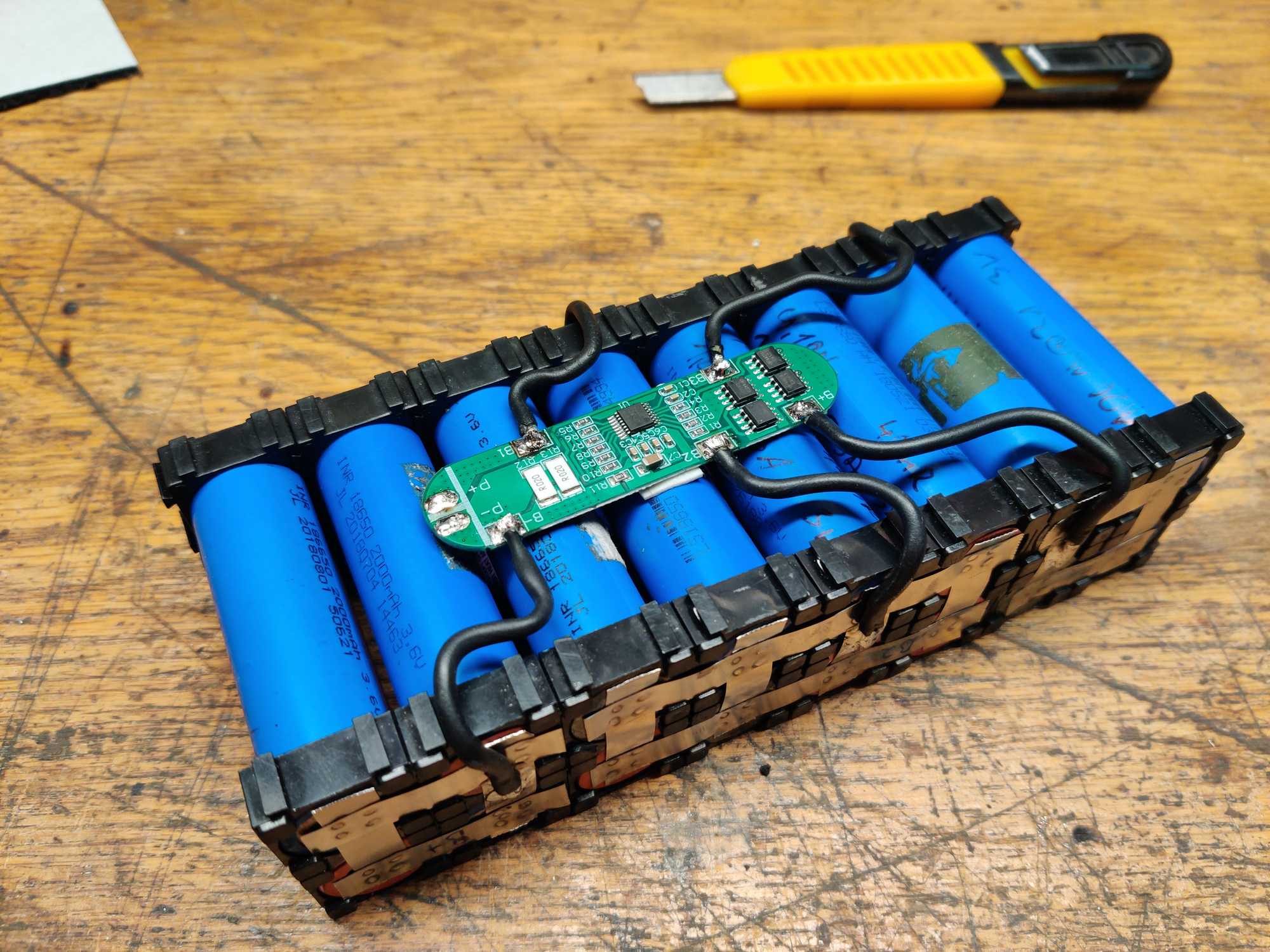
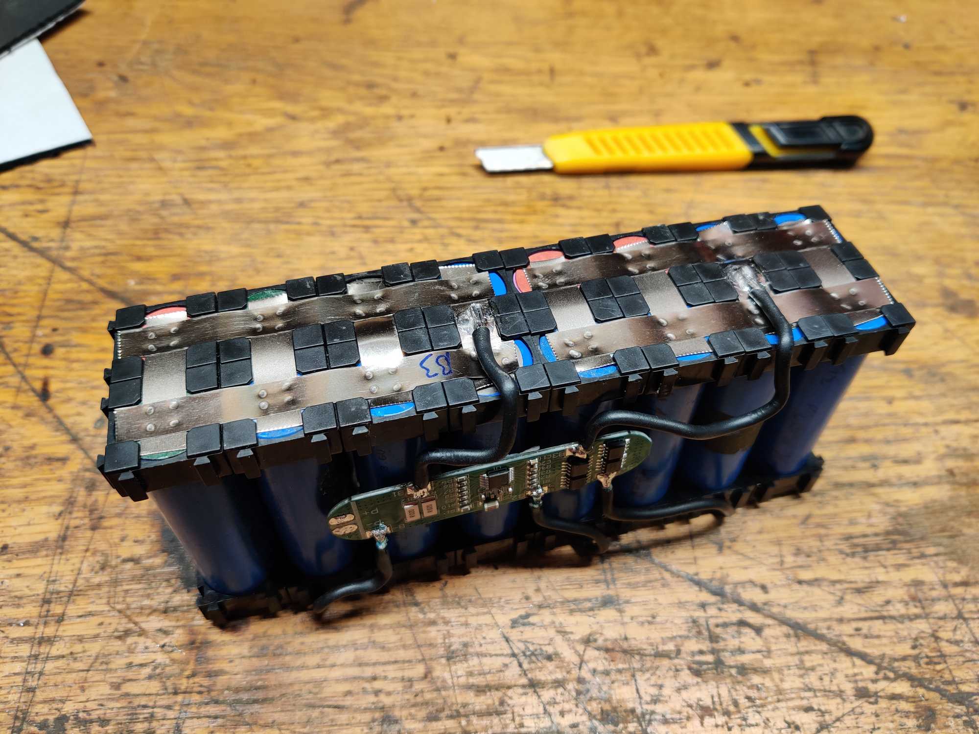
Next up I made a 4S4P battery of refurbished LiPo cells. They weren’t in a very good condition so the biggest capacity of some were 1.5Ah when tested with a load of 3A.
The battery was assembled into a bracket (I used a neat tool https://www.repackr.com/ to organize the cells properly) and spot-welded together after which I added a 4S BMS.
By the way the BMS I used has an interesting undocumented feature about which I was scratching my head for a while and thought I somehow fried the module. The problem with it was that once all cells were connected there was no voltage output… I even bought another BMS but had the same result and that’s when I turned to internet for help.
After browsing for a while I found out that for some of these BMS modules you have to activate them by giving them voltage to the charge terminals. But the voltage also has to be around 16-17v and that activates the BMS immediately.
Another reason why the BMS doesn’t output voltage might be that the cell voltage is too different. I read that also and one of my cells were 4v while the rest were 3.8v so before trying to activate the BMS I discharged that one cell to around 3.8v on a load tester and then connected my BMS.

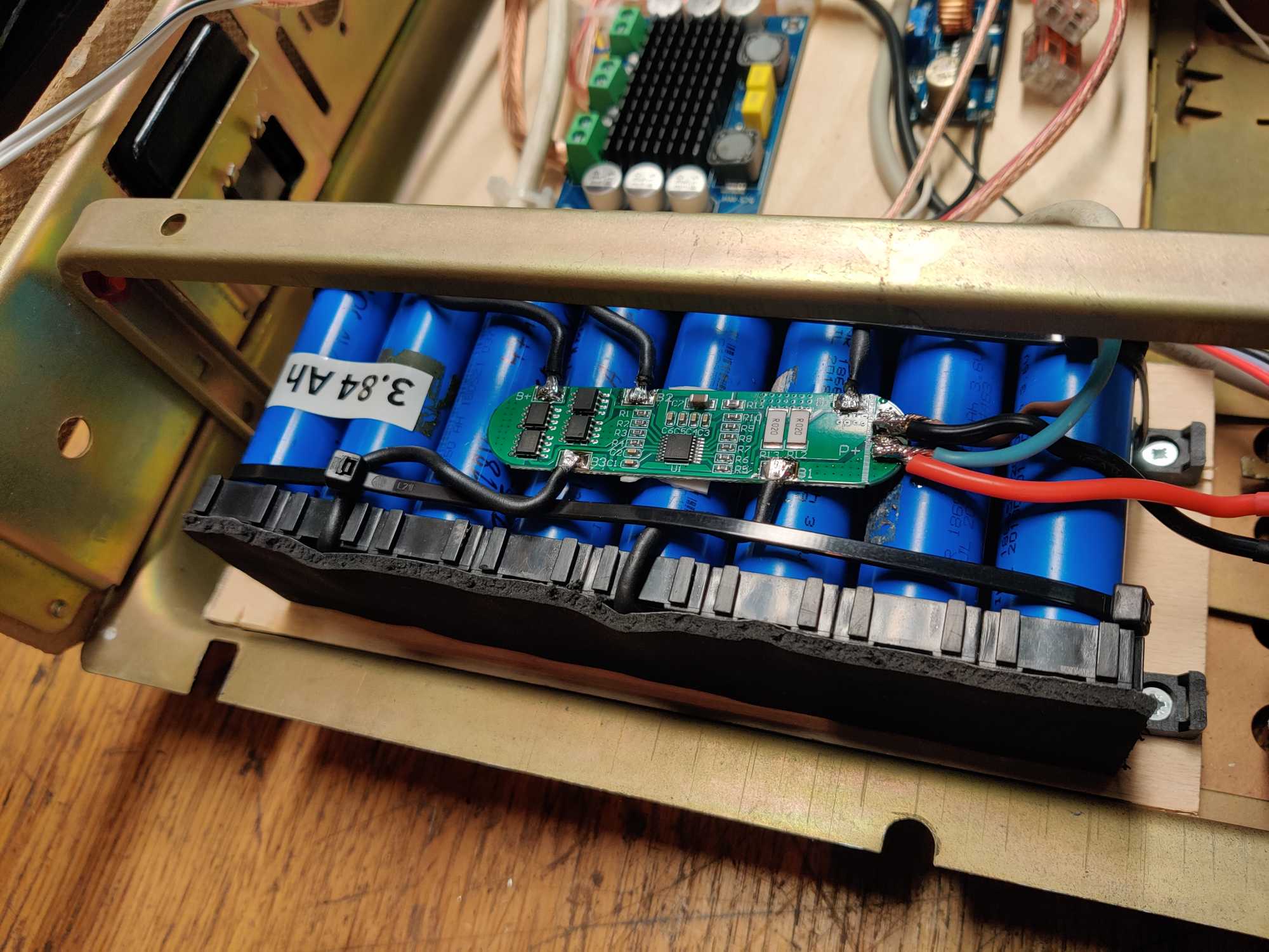
I tested this battery pack on a load tester with 6A to check its final capacity and it was 3.84 Ah but it could have been around 6 Ah. Because of one bad cell that discharges much faster than others the voltage has to be cut off sooner. That’ll have to do, I don’t want to disassembly the whole thing.
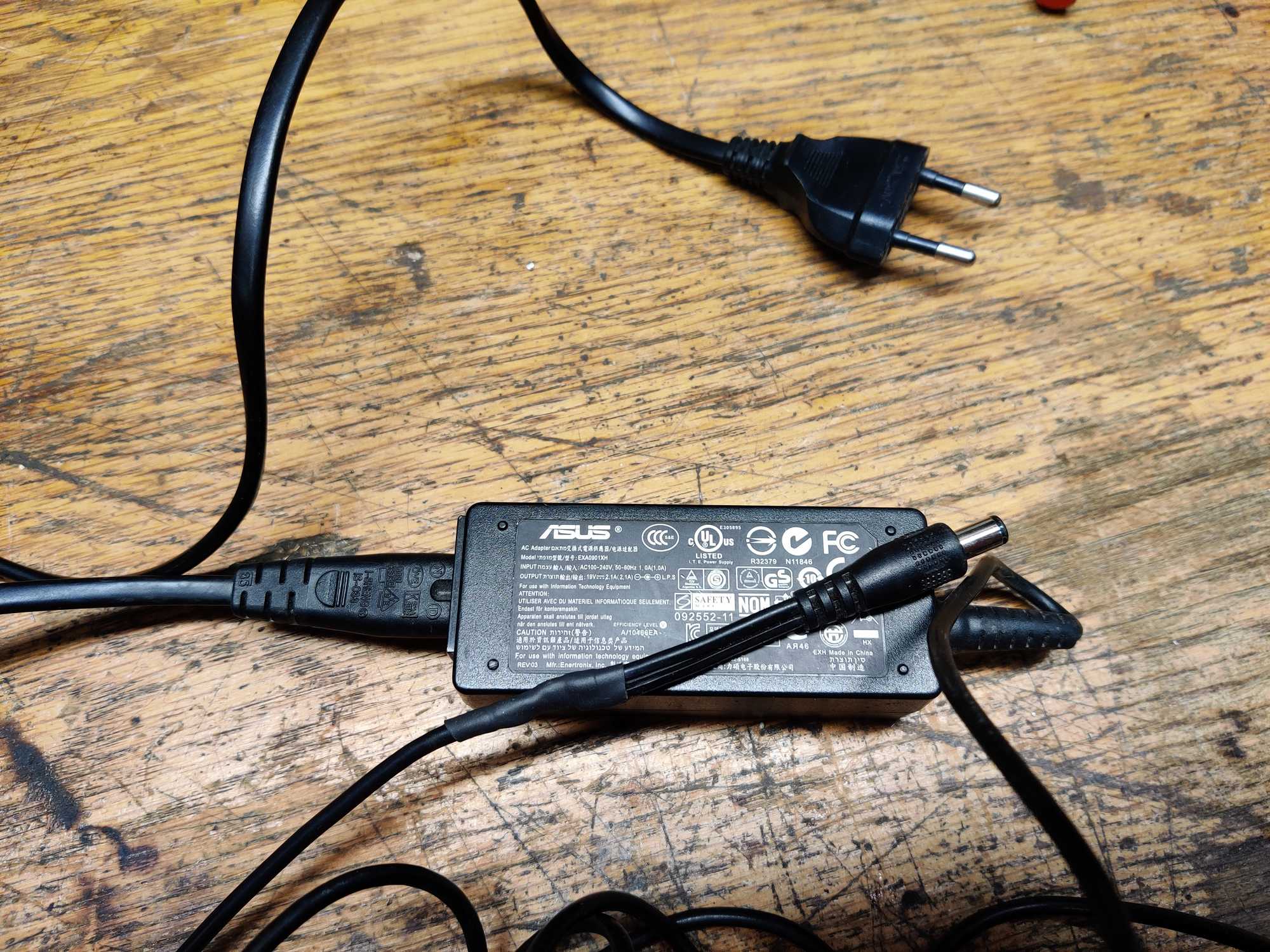
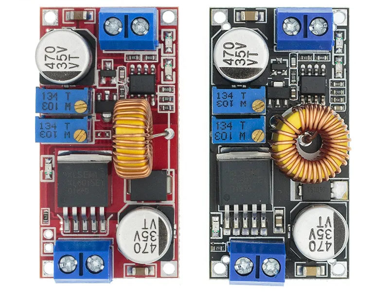
And the power source. It’s a generic laptop charger with 19v and 2A output, but to actually use it you cannot connect that directly to the battery because the BMS having a 6A output will try to draw 6A as input as well and overload the charger which might block itself until disconnected. So what do you do in such case? you use a buck converter capable of setting a constant-current which will protect your charger from overloading by limiting how many amps to draw from your charger.
After using it for a while I encountered some issues that I didn’t really thought through…
First part to give out was a buck converter which was much too small for this application and died. I found another beefier one in a drawer to replace it.

Then when I replaced it the bluetooth module’s DC-DC converter was fried and I had to make a different one. Luckily I had all the parts needed. One thing to remember though is that you cannot put heavy things on the turntable. Because it is being turned by a rubber wheel, that wheel sometimes gets stuck and the motor makes a dent in the rubber and then it starts to make annoying clicking noises when turning.
But now that’s it all done, it looks pretty cool.