When we made the MFM v2 we only made a release button to operate the machine – same story as with v1 because we didn’t actually have time to do more than that and we were unsure of how it’ll work in the field. This year we decided to do a remote controller and a timer.
I wrote about the previous version of it here for the MFMv1 which was controlled with a phone through WiFi and that’s fine but it’s a bit too advanced for such a basic task, moreso if we wanted to lend it to someone. The way we did that wasn’t very reliable because it would sometimes crash or disconnect out of nowhere and it might have been the reason for MFMv1’s eventual demise.

This year I thought about how to make it more basic and learning from previous years I only wanted for it to have a timer function and a remote controller with a 433MHz radio module. The very same principle as any fog machines on the market use.
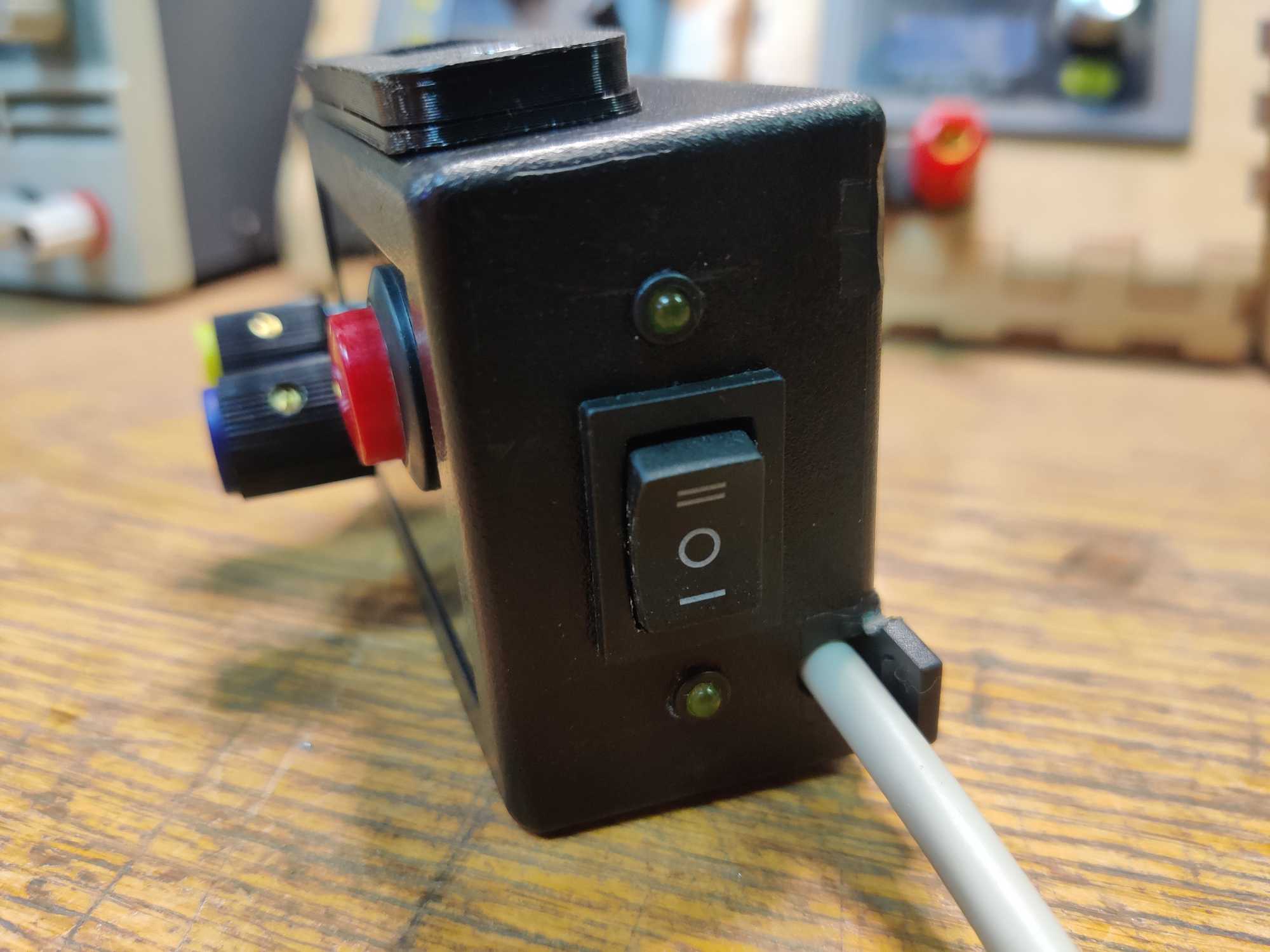
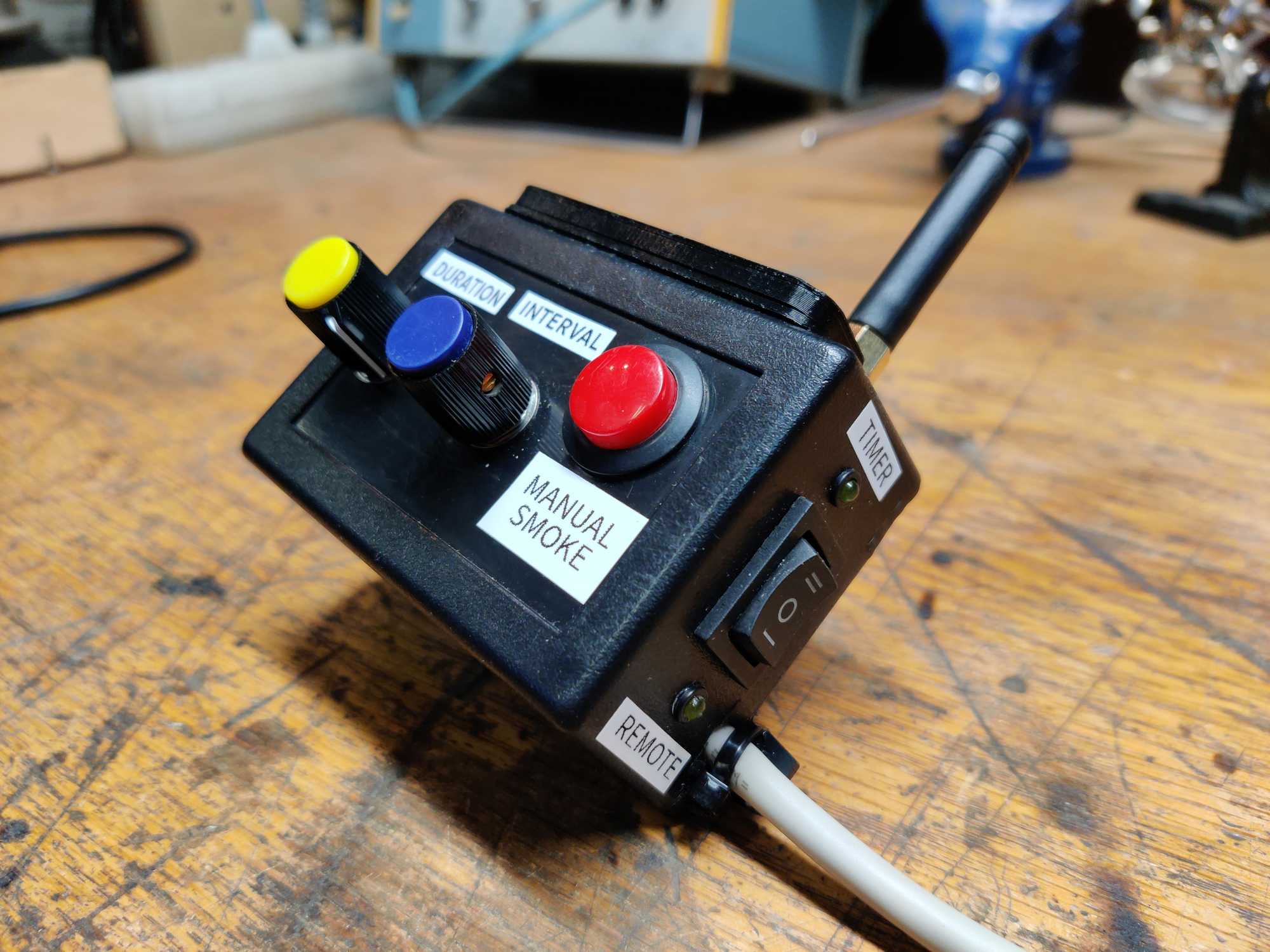
It would need to have a 3-way switch to select between a timer and remote control with the middle position to turn it off and of course for convenience – a button for manual fogging.
Since having the remote control was done by buying a cheap and small radio module I started with making the timer using ATTiny85, two potentiometers and an OLED screen. Pots would control interval time between sprays and duration time for how long to spray fog. Pot status is shown on the screen. However though, after testing it for a while I noticed that sometimes the potentiometer reading would drift and become inconsistent, therefore unreliable. Using rotary encoders for this would of been much better but that also adds more complexity to the whole thing and I would need two of them. I’ll need to solve this with some logic or figure out how to make a stable DC power input.
First off as usual I connected everything on a breadboard and started coding.
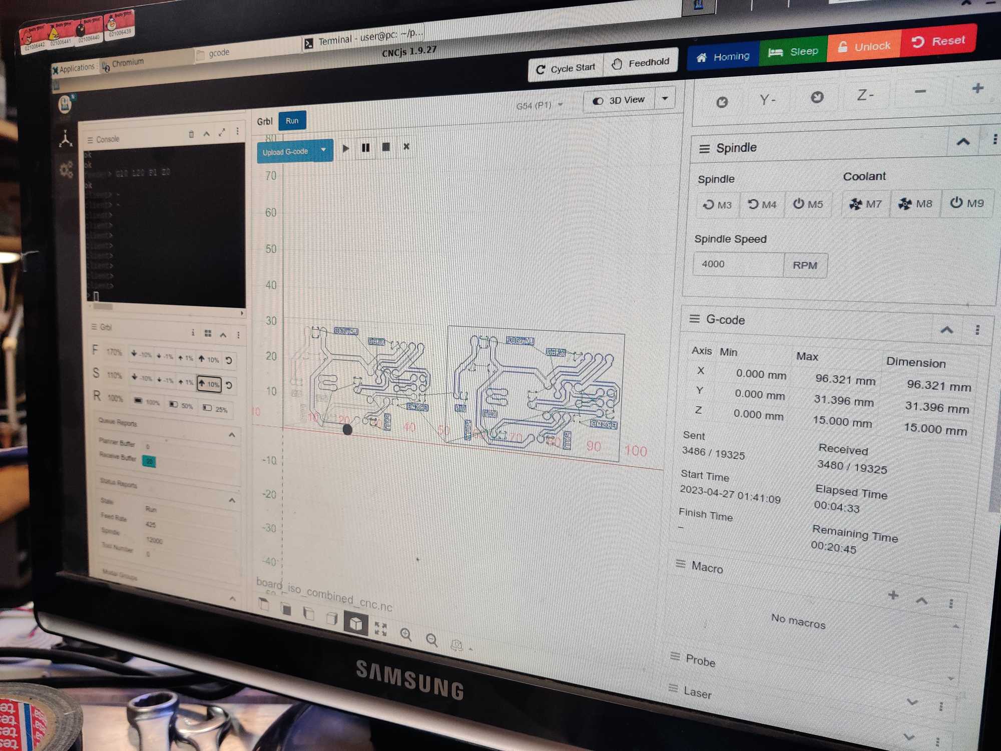
With programming done next I needed to make a PCB for it and just recently few people here at the Kaunas Makerspace made a CNC which can also be used for PCB milling and that’s what I used for this project :) if not then I would go the usual acid etching way but this time I wanted to try out milling because I never done it and that seems pretty awesome.
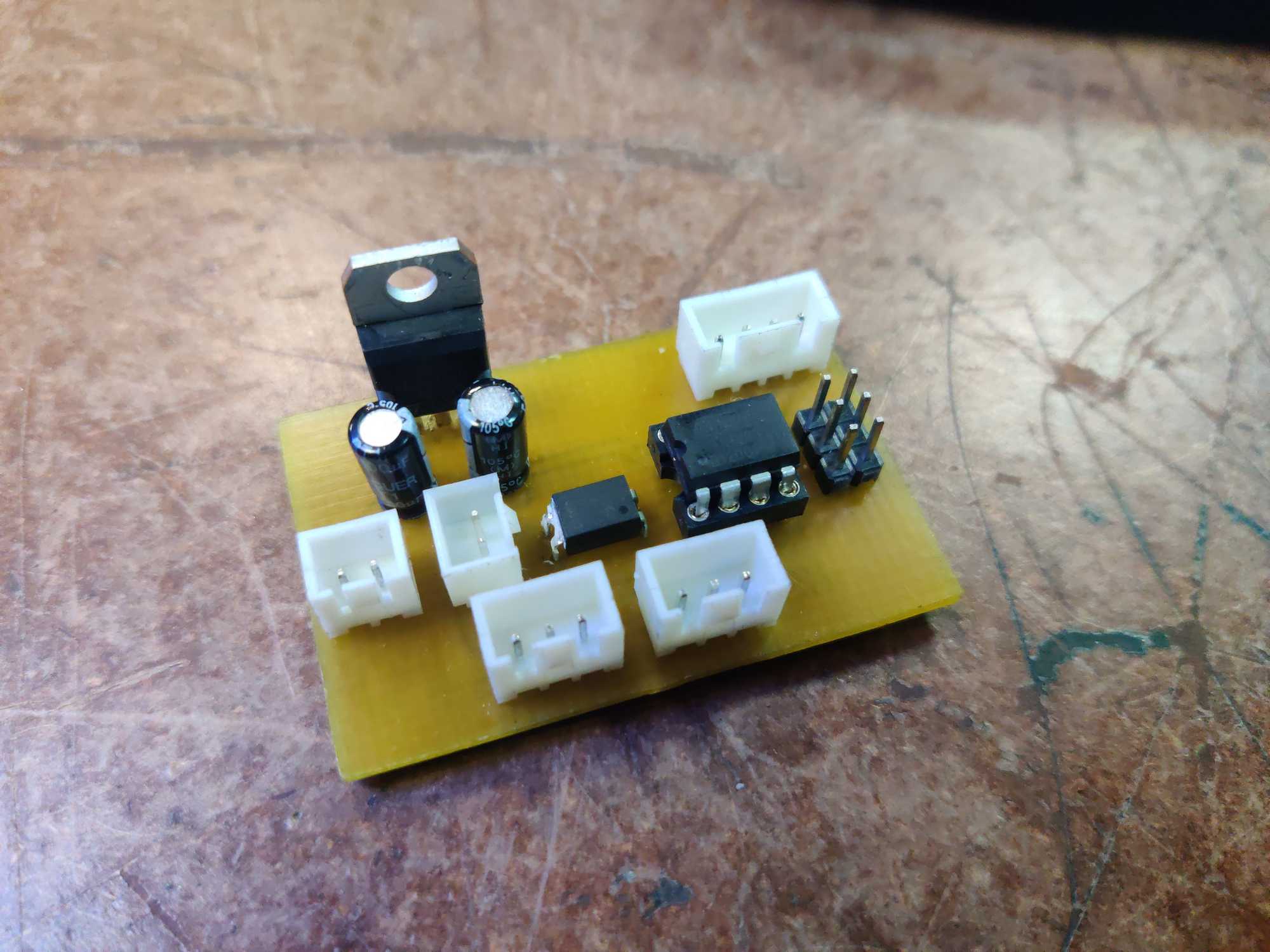
I made the schematic and a PCB layout and then exported the Gerber and Excelon files, loaded onto the CNC and started milling. It took me more than a few tries to get it right but eventually I did it and a big bonus with milling is that you don’t need to drill holes yourself anymore and they come out perfectly sized :D


And this is how it looks assembled:
The code for this little piece can be found on KMS’s github: https://github.com/makerspacelt/monster-fog-machine-v2-remote-controller
As for the wireless relay – I bought a tiny one on AliExpress for very cheap. But after using it for a while I’ve noticed that the range is very poor with the stock antenna, so I’ll have to attach one on the outside.

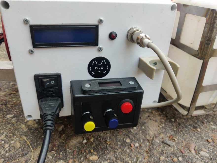
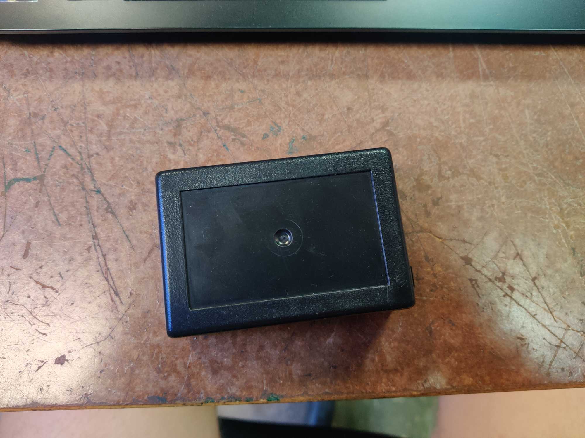
Having the main components ready all I need to do is assemble everything together into a plastic project box so I started drilling and cutting away. One thing that bugs me is that the smaller OLED display is kinda not the type of a part to be attached easily like the 16×2 LCD display. I found a frame for it in Thingiverse which is great for this, though could of been 1mm higher because I needed to make an extension to raise the frame a little.
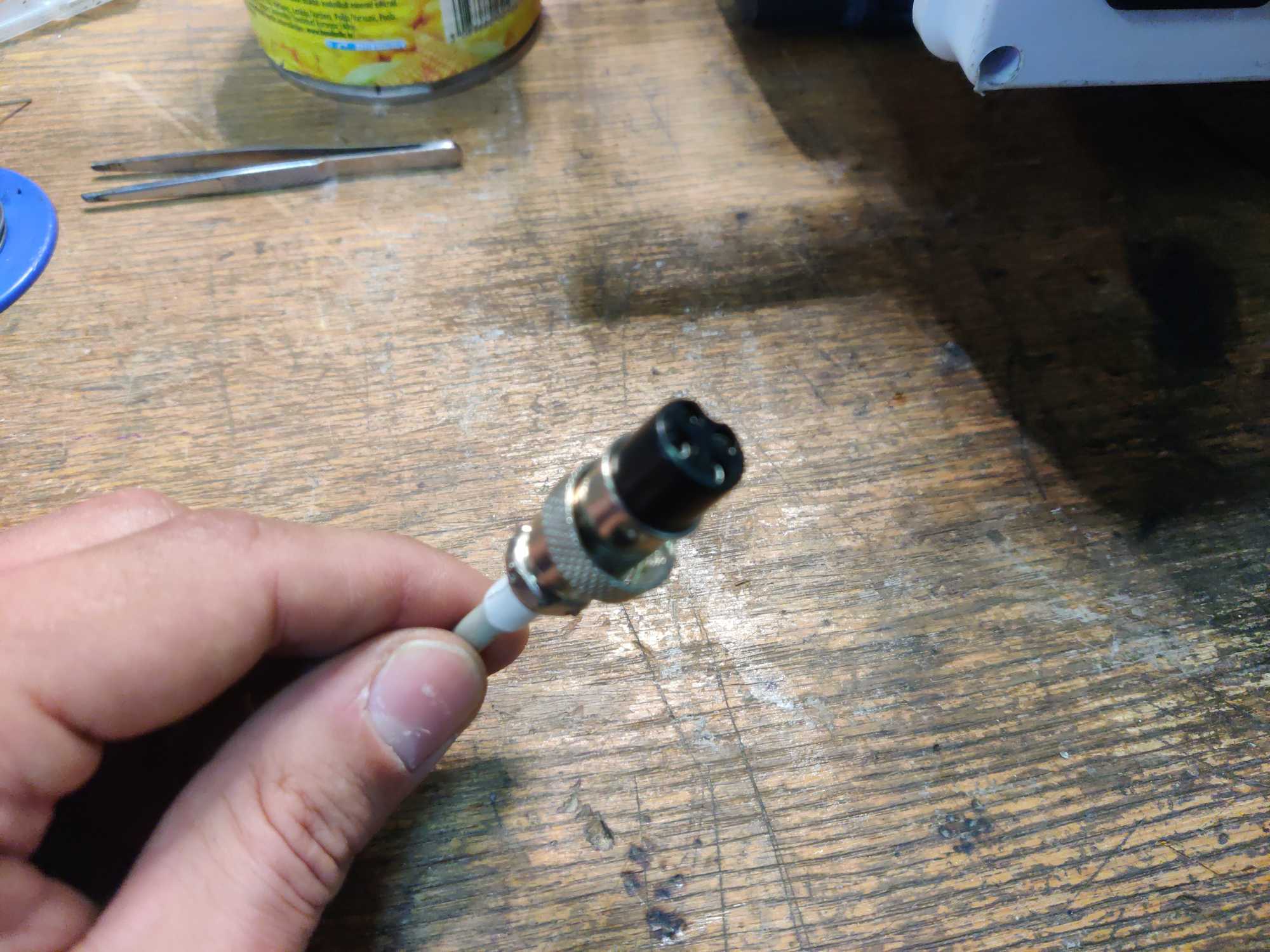
To power it up I used power from the main box through the same connector but I had to replace that with a 4-pin version to support signal and power.


Right, so later I found a couple of bugs in the PCB design that I didn’t think about before.
First, 5v supply should be connected for easier programming, I fixed that with a jumper wire for now.
Second, the optocoupler (COSMO K1010) that I used needs to have a resistor otherwise the programming won’t work if you have it connected to the same lines used for programming.
The resistor value was calculated by looking at ATTiny85 and optocoupler datasheets and observing that the ATTiny85 can properly supply around 10mA at 5V according to the Atmel test results and optocoupler needs 20mA at maximum to fully work. But we don’t need it to be working at maximum so I guessed that about 5mA should work for my purposes.
Also looking at the datasheet we see that the optocoupler typical voltage is 1.2v so we need to reduce the output voltage to that.
So 5 – 1.2 = 3.8. Now 3.8 / 0.005 = 760 ohms is our theoretical baseline. I didn’t have a resistor of that value so I used the next best thing – 1k ohms but that proved to be not enough because the MCU would still not respond. Then I increased that to 2.2 kOhm and that was too much – the optocoupler wouldn’t trigger but the programmer now responded. Finally I tried 1.5 kOhm and that was where it worked great with MCU responding and optocoupler still triggering.

Obviously it needs a way to be attached to the main block and so I made and 3D printed a holder.


So finally the whole thing looks like so