
This project derived from another one I made some time ago which was a portable music player, though I had this radio much before I made that other project, but I didn’t know what I would want to do with it.
The radio that I have is a VEF Spidola 232. It was to be thrown out as trash, but I thought I could maybe add some modern stuff to it, and stashed it in a corner until I figure out what I’d like to do with it.
On the internet there are some people that do this and they have pretty cool ideas turning these radios into things that can play from various sources leaving the whole shell and buttons original. Some even remake them to be used with FM frequencies.
My idea was similar, but I only wanted it to have bluetooth and I don’t need anything else. Also I wanted it to have a better sound quality (original speaker is just shit) and leave everything else original as much as possible.

It works like this:
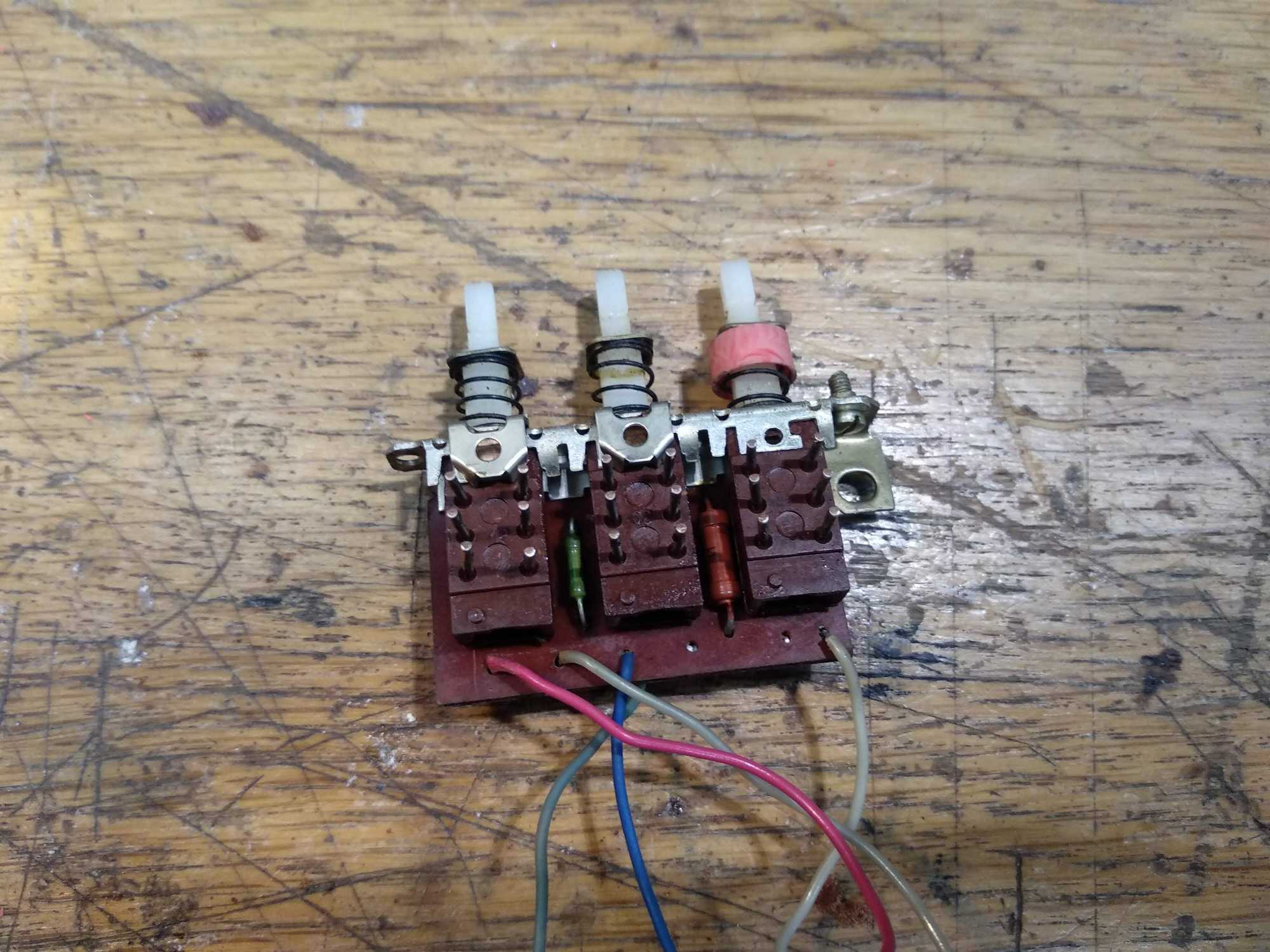
This radio has three buttons on top. First one is for momentary light (it would illuminate the “screen” but I’ll use it to check battery status), second one is the power button, and third one is a setting to control the timbre.
Big dial on the left controls the volume and a dial in the middle of that big dial controls the timbre (I don’t know what that was supposed to actually be).
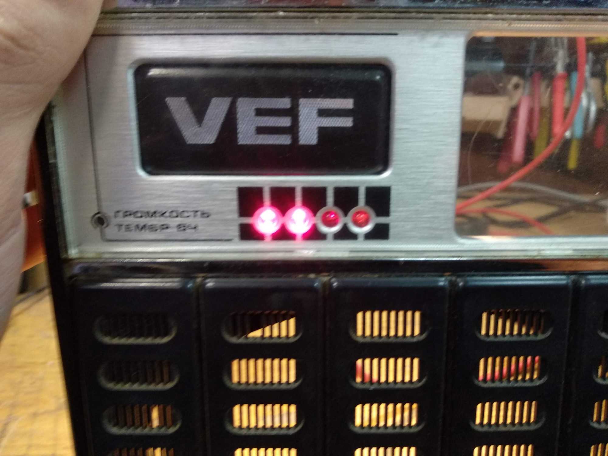
Four LEDs show a signal status somehow, but I’ll make that to show battery status.
Then on the right, the top dial selects a frequency range and there’s a dial on the bottom right side that is used to tune the radio to some frequency.
It was powered from batteries or from a 9V power source and had a headphone socket (which is going to be replaced with audio-out socket) along with other sockets for, what appears to be, a recorder and an external antenna.
Upon opening the back cover, we are greeted with this sight:

Gotta love the hand-drawn tracks :D
And the whole mainboard looks like this:
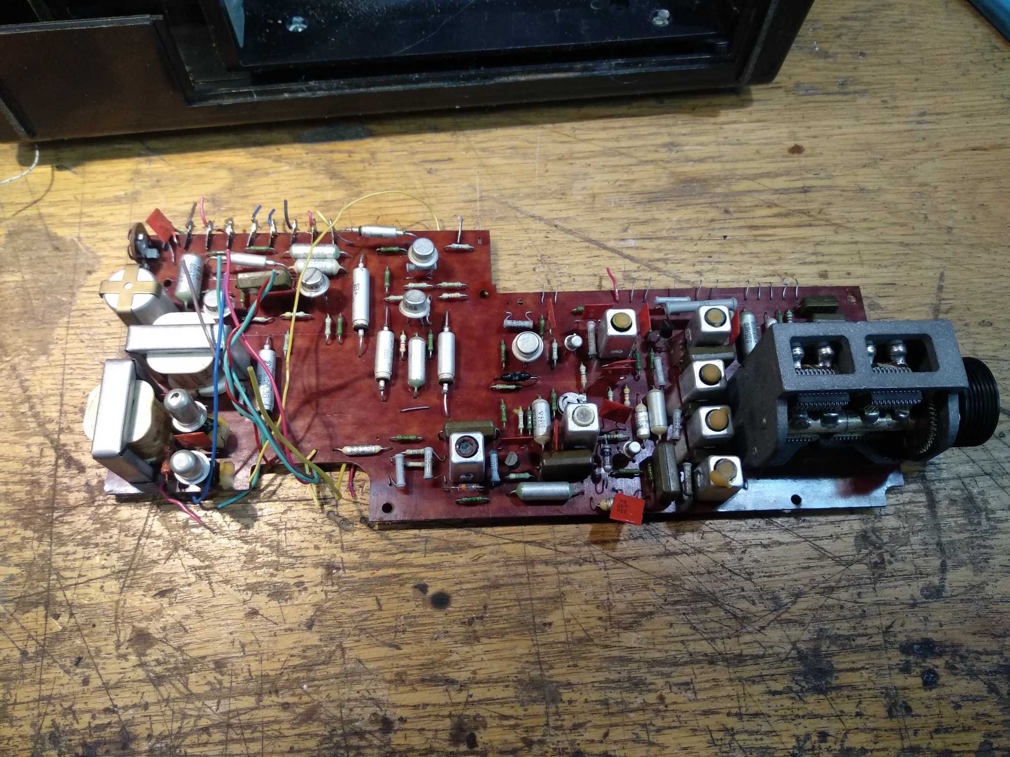

(second picture is the frequency tuning dial thingie)
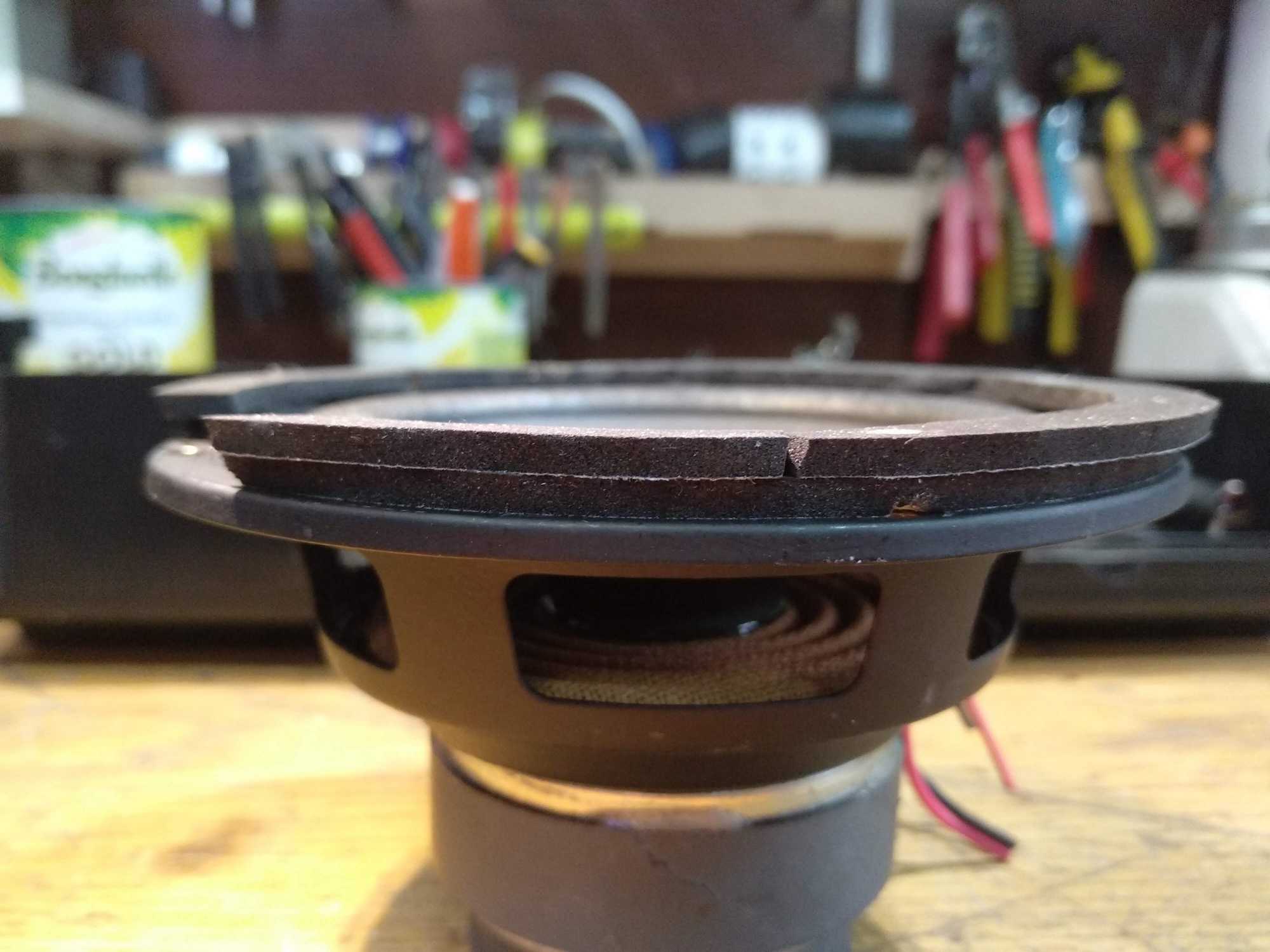
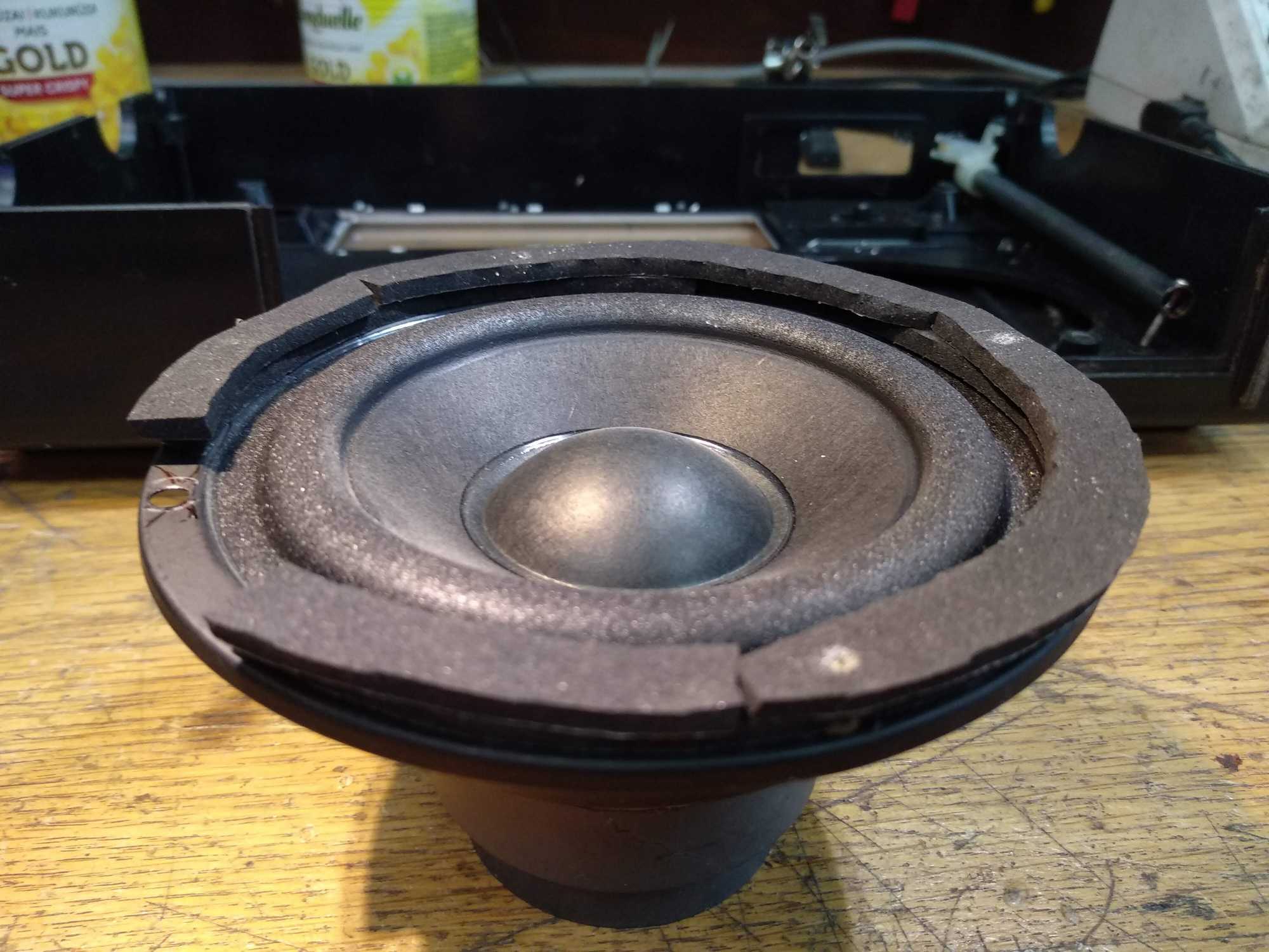
For the speakers, I had this one part of Microlab B77BT desktop speakers and took it apart. This setup usually comes in pairs, where one being the main speaker with an amplifier and volume control. This one was left out because the main one was destroyed and thrown out.

Since this speaker was 15w, I ordered a capable amplifier (model ZK-502L) with bluetooth and volume control built-in and decided to make everything 12v powered for best results.

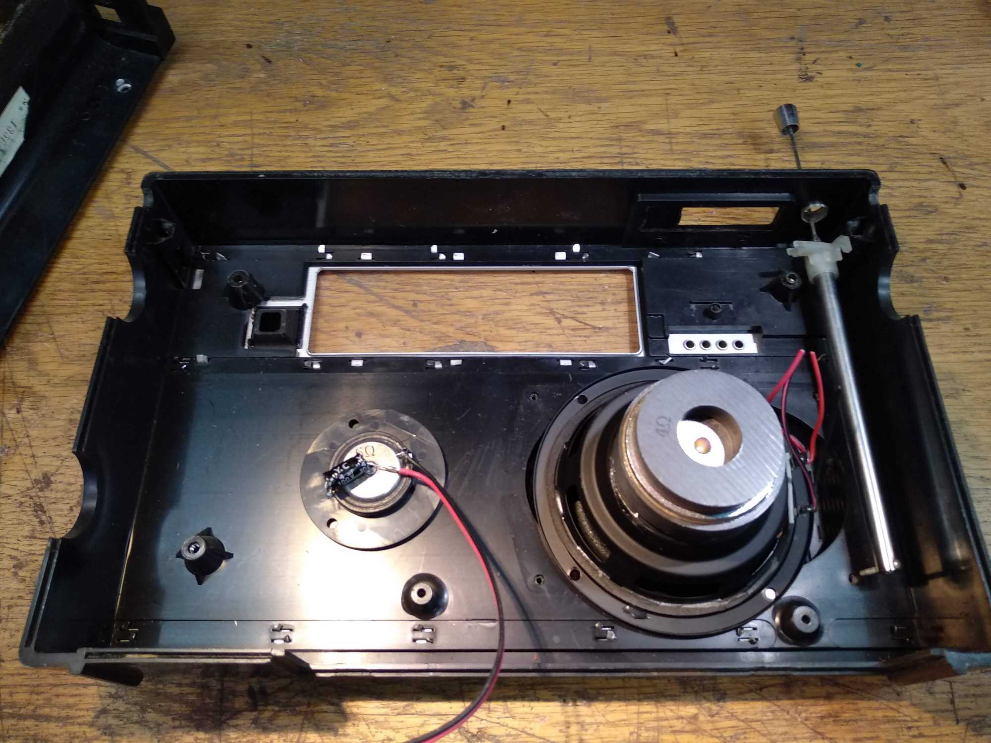
The first thing I did with this radio was I took it apart, thrown out everything from inside that wasn’t going to be used and was left only with an inside bracket where everything was mounted on. I’ll leave that because it holds up some dials and whatnot. Right away I saw that speakers, batteries, amplifier should fit right in without much hacking, though I’ll need to cut up the bracket a little to accommodate the new speaker which is slightly larger and batteries too.
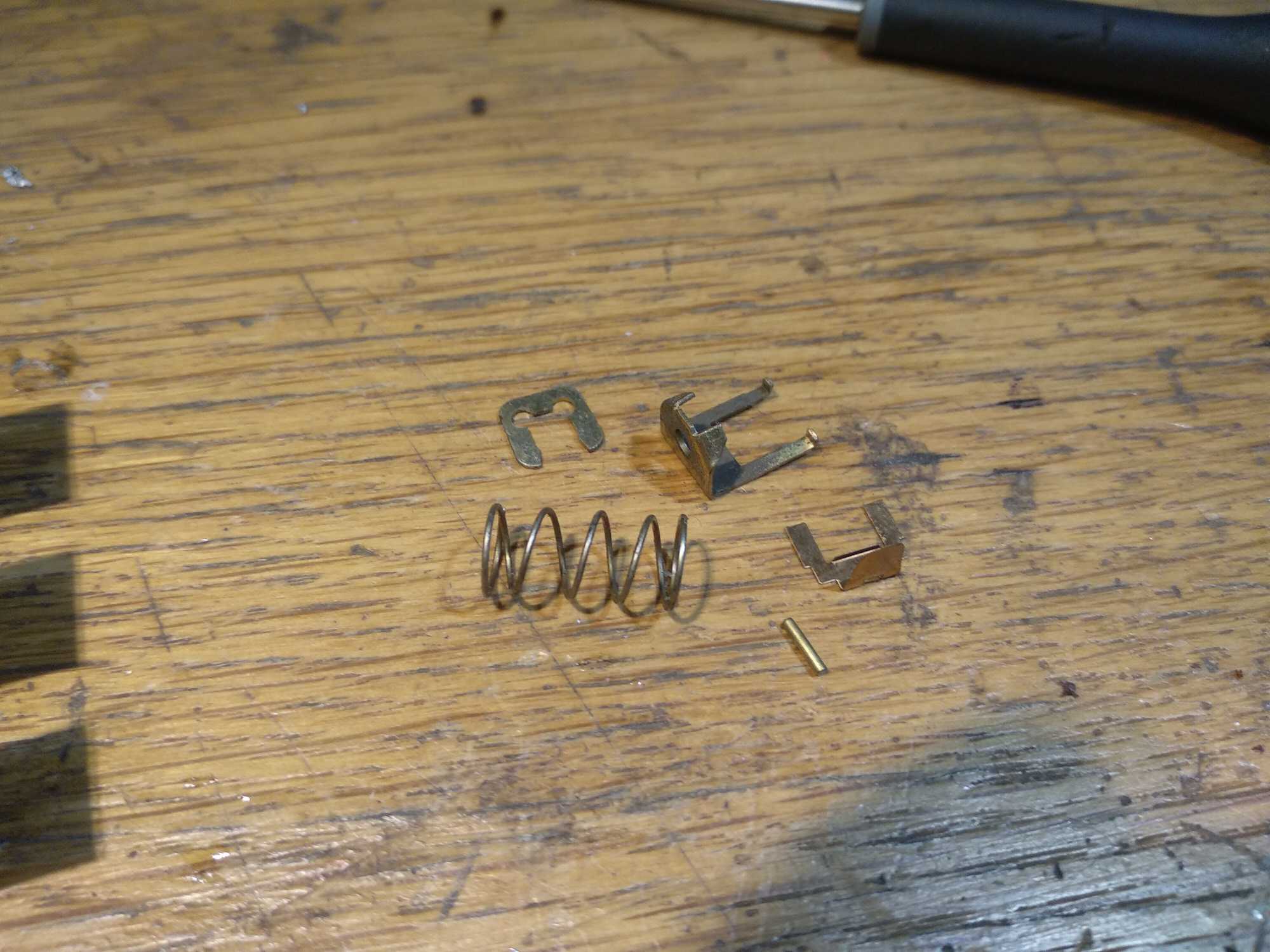
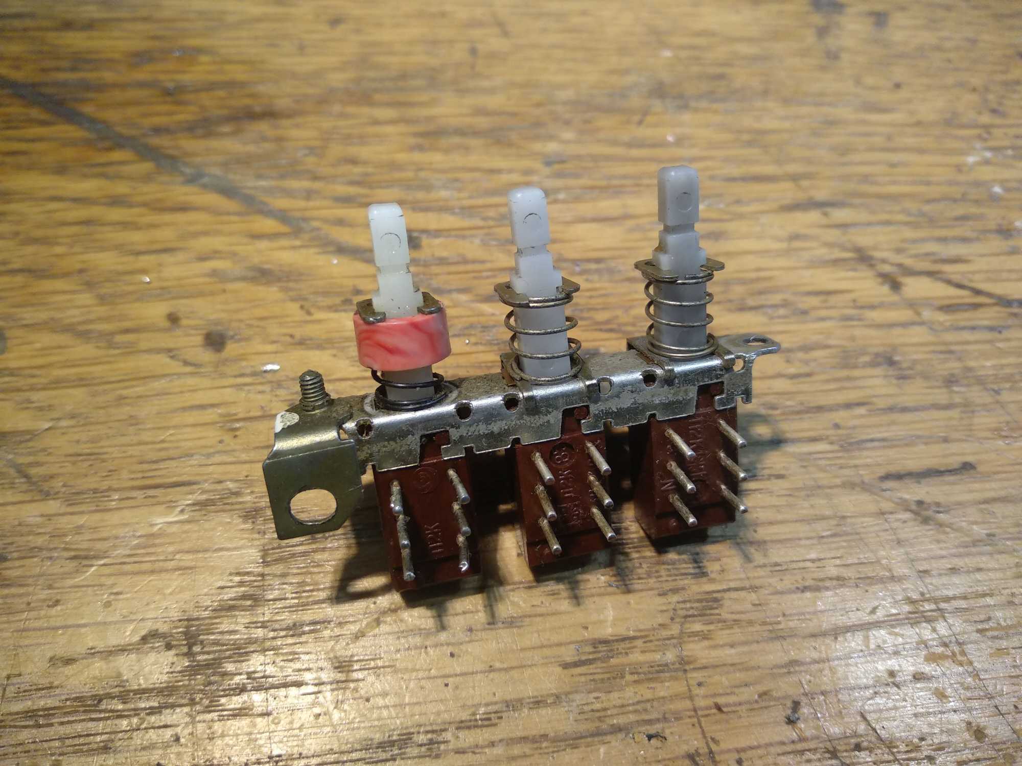
The top buttons were a bit dirty and the middle one that is supposed to turn on this radio didn’t fixate very well, but the one for timbre works good. I wanted to switch them up because I won’t be using the timbre button for anything. But they are made in such a way that you’d need to remove retaining rings with a spring before they can be removed from the bracket. And if you’re not careful (like me) you can lose some retaining rings, the spring and the whole things can’t be assembled again if you push out the middle part… soviet design, what can I say.
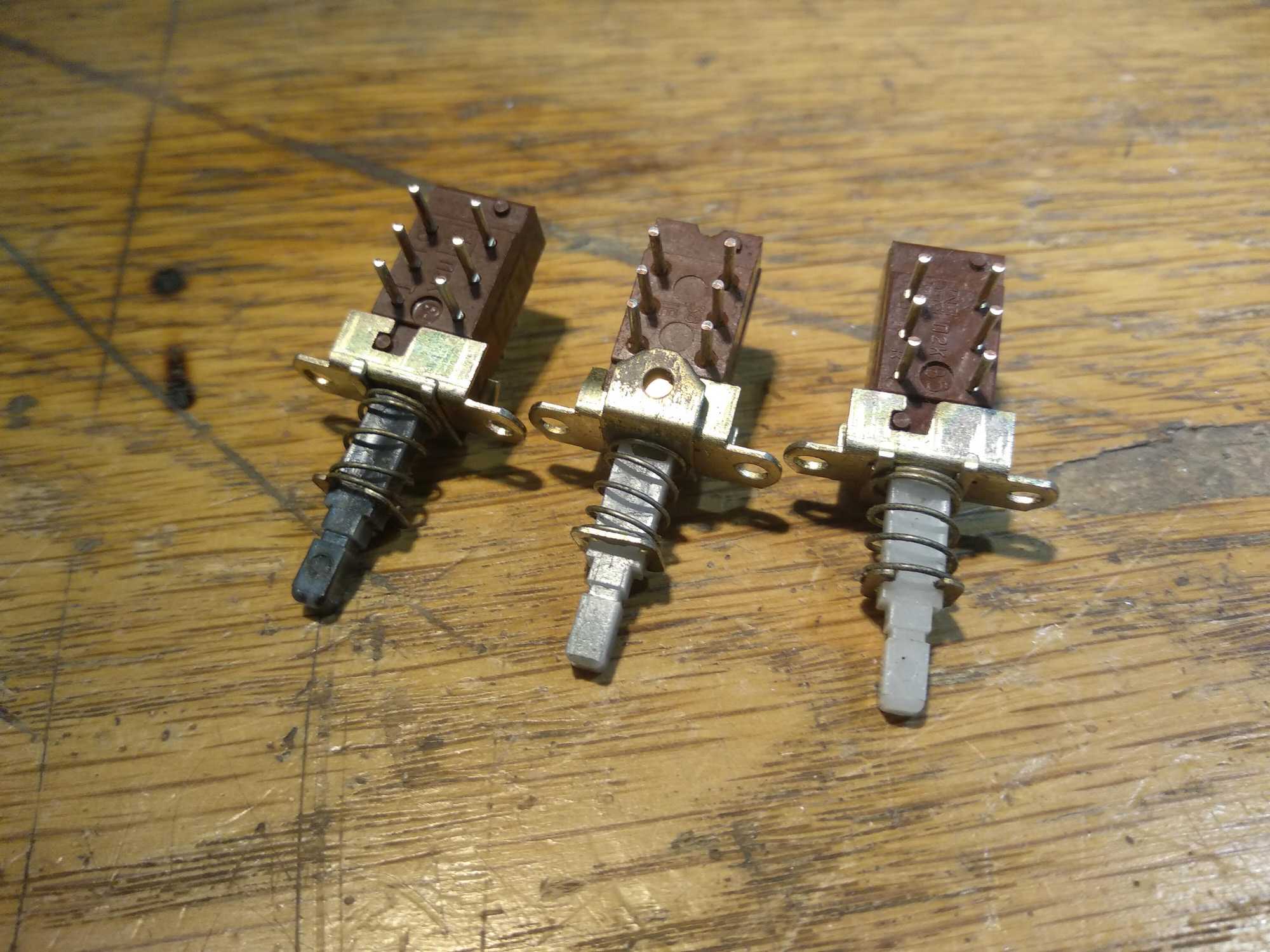
Lucky for me though, Evita still sells these P2K buttons which I bought three. RCL sells modern compatible ones.

Along with buttons I also bought four red LEDs that have a similar shape to use in-place of old ones that were supposed to show some kinda signal strength. I would of used the original ones, but one LED didn’t work, therefore I decided to replace all of them instead.
I’ll re-purpose this feature to show battery level.
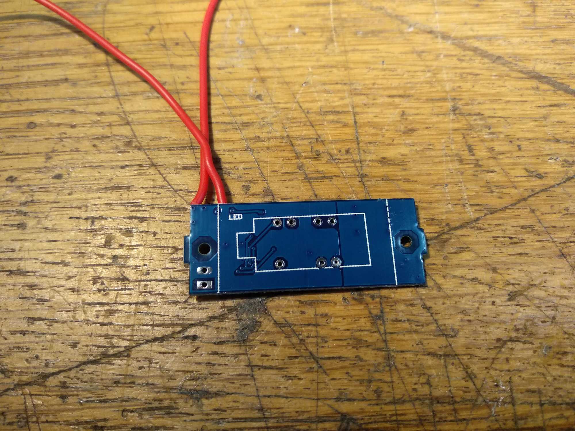
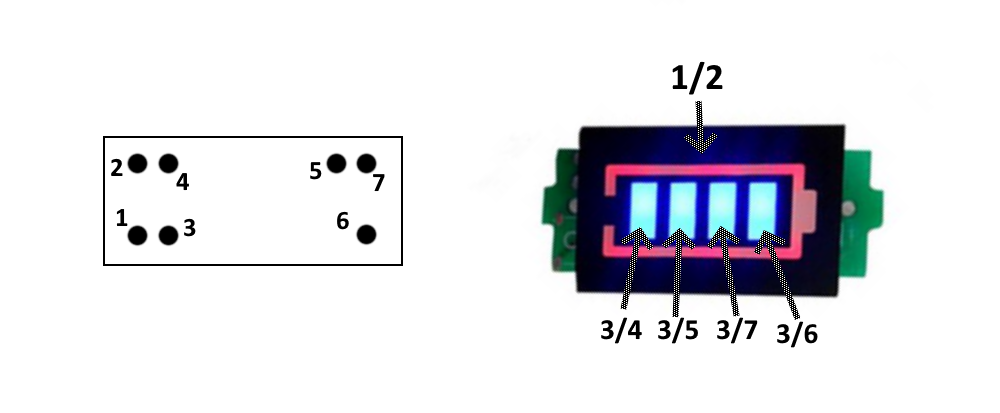
To actually show the battery level, I used a display that does just that and it has four LEDs as well. Though to use it here, I had to remove the little screen that came with it (note the pinout) and solder my own LEDs in place. This module gives out 3.8v on each pin, but that is way too much for an LED, which takes in 3v at max and with this voltage they’ll be annoyingly bright. I reduced this to 2v by adding 200ohm resistors on each of LEDs.
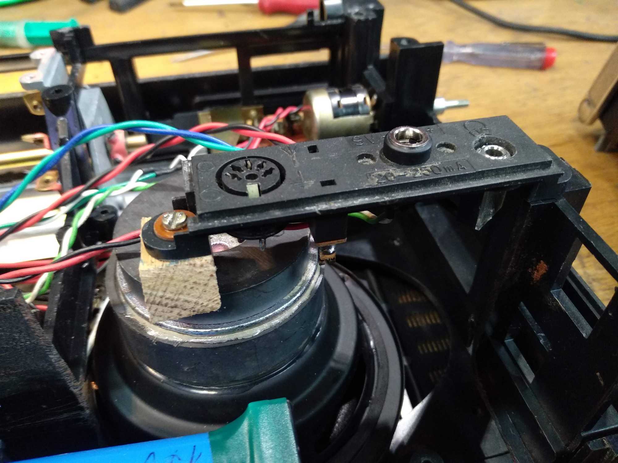
This is the module that needs replacing. I only kept the bracket. Removed the screen from battery meter module and connected my own LEDs.


This is the pin diagram for this module:
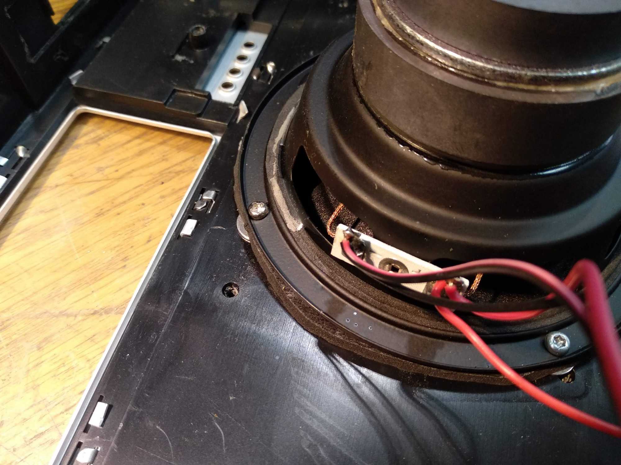
After this I planned how I’d mount the speakers inside. The big one wasn’t a problem – I only had to drill new screw holes and cut out a bit of the bracket. For the smaller one I had to cut a new hole for it. And I also added some padding to lift those speakers up a little.


With that done, I then made a 3S LiPo battery, to have 12v.
To do that I used some old laptop cells that were still quite good (1.5Ah for each cell, discharged @ 3A so there should be around 4Ah of capacity in total). If you have cells that are not around the same capacity, this tool can be used to help you determine cell placement in a pack: https://www.repackr.com/#/pack-builder
I used a spot-welder to connect cells into a battery and used a 3S BMS to manage this pack and placed the whole thing on plywood, just for them to be sturdy.

The amplifier is great for these speakers, the sound is very nice, there’s no hiss or any other noise that you could hear due to ground-loop (when powering off the batteries usually). But this amp does not support connecting one speaker to both channels (L and R) – if you do that, it won’t output any sound. Because of that I only connected to L, still the sound is pretty nice and loud.
With this setup I can’t combine both channels with resistors as well, because the signal output from the amplifier is much too strong. Only solution now is in your phone settings to set Mono audio.
In the future it’s better to use a bluetooth module and an amplifier as separate modules, then both audio channels could be combined directly from a bluetooth module and into the amp.
Also I replaced the old thread with new, to have a functional frequency dial again. Obviously it doesn’t do anything :D
And finally started assembling everything… (btw to understand how the audio jack switch works, follow this article)
Also note that I connected it from the amplifier output, which means that the outgoing signal is much too strong for a line-in.
To make the signal weak enough not to fry your device, you need to make a voltage divider with a pair of resistors.
The resistance can be obtained by first connecting a potentiometer and turning the dial until the sound you hear is good and isn’t distorted. After that just measure the resistance and use appropriate resistors. In my case it was 10k and 7k.


I left the screen illumination unconnected. At first I thought of having them shine whenever battery status button was pressed.
Anyway, result is pretty nice. The sound quality is nice overall and I assembled it mainly from stuff that was laying around. I only bought the 3S BMS, a battery status indicator, some LEDs, few switches and the amplifier. In total I spent ~10 euros.

